POLARIS II LAMINATOR OPERATOR MANUAL Part Number: 930-115 REV: - REV Date: 7-27-04 © 2004 GENERAL BINDING CORPORATION. ALL RIGHTS RESERVED. Do not duplicate without written permission.
The information in this publication is provided for reference and is believed to be accurate and complete. General Binding Corporation is not liable for errors in this publication or for incidental or consequential damage in connection with the furnishing or use of the information in this publication, including, but not limited to, any implied warranty of fitness or merchantability for any particular use.
Operations Manual Polaris II Table of contents 1.0 Safety 1.1 Explanation of symbols 1.2 General rules of safety 1.3 Labels Figure 1.3.1 Safety label placement 1-1 1-1 1-3 1-5 2.0 Warranty 2.0 Warranty 2.1 3.0 Specifications 3.1 Film and sheet size 3.2 Functions 3.3 Weight 3.4 Dimensions 3.5 Electrical requirements 3.6 Recomended work space Figure 3.4.1 Dimensions 3-1 3-1 3-1 3-1 3-1 3-1 3-2 4.0 Installation 4.1 Pre-installation 4.2 Setting up your laminator Figure 4.2.1 Paper Guide 4-1 4-2 4-2 5.
Polaris II Operations Manual 6.0 Applications 6.1 Film loading and threading Figure 6.1.1 Suction Cup Control Figure 6.1.2 Suction Cups and Paper Stack Figure 6.1.3 Film Leader 6.2 Helpful hints 6.3 Important points to remember Quick Set up Application Guide 6-1 6-1 6-1 6-2 6-3 6-3 6-5 6-6 7.0 Maintenance and Troubleshooting 7.1 Cabinets and cover 7.2 Clean the rollers 7.3 Misc Maintenance 7.4 Troubleshooting Figure 7.3.
Operations Manual Polaris II 1.0 Safety CAUTION: Do not attempt to operate your Polaris Laminator until you completely read and understand this Operations Manual. Your safety, as well as the safety of others, is important to General Binding Corporation. This section contains important safety information which must be adhered to while operating, cleaning and performing basic maintenance in and around the machine. ELECTRICAL HAZARD: [This symbol is used prior to a step.
Polaris II WARNING: Never use this machine for any other purpose than its intended design and function. CAUTION: Do not make any modifications to this laminator. Unauthorized changes will void your warranty and may cause extensive repairs or create poor output quality. WARNING: Do not attempt to repair or service the laminator. Disconnect the plug from the power receptacle and contact your local sales/ service representative.
Operations Manual 1.3 Labels Safety warning labels are placed at various locations on the laminator. Do not remove any of these labels. They are placed for your safety as well as the safety of those working around you. Below are illustrations of the safety labels and a description of their meanings. Polaris II This label is located on the rear panel in the center of the laminator just below the film supply shaft between the pull rollers and decurling bar.
Polaris II Operations Manual – The safety label below means that you could be seriously injured if you come in contact with the moving chain and sprockets of the drive system. This label is located near all drive sprockets on the machine. Sharp knife – The safety label below means that you could cut yourself if you are not careful. This label is located on the rear panel in the center of the laminator just above the Electrical hazard safety label and below the rear slitter. Refer to Figure 1.3.
Operations Manual Polaris II Figure 1.3.1 Safety label placement (2) O ne on each side of the lam inator (1) B etween pull rollers and decurling bar (1) C enter rear panel below film unwind.
Polaris II Page 1-6 Operations Manual © 2004 General Binding Corporation
Operations Manual PolarisII 2.0 Warranty GBC warrants to the original purchaser for a period of ninety days after installation that this laminator is free from defects in workmanship and material under normal use and service. GBC’s obligation under this limited warranty is limited to replacement or repair, at GBC’s option, of any part found defective by GBC without charge for material or labor. THIS LIMITED WARRANTY IS IN LIEU OF ALL OTHER WARRANTIES EXPRESSED OR IMPLIED.
Polaris II Operations Manual This page intentionally left blank.
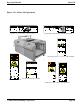
Operations Manual Polaris II 3.0 Specifications 3.4 Dimensions (W x H x D) Refer to Figures 3.4.1 Dimensions. This section provides specific information regarding the laminator. Any specification not provided must be requested from GBC. Machine – 50.5 in. x 54 in. x 85 in. – (128.25 cm. x 137 cm. x 216 cm) – 105” long with delivery table 3.5 Electrical requirements 3.1 Film and sheet size Film – Single side films (ie., GBC LAYFLAT, GBC HI-TAC) Core – 3 in. (7.6 cm) Sheet Size – Min. 11.0 in.
Polaris II Operations Manual Figure 3.4.1 Dimensions 5 4 in c h e s 1 0 5 in c h e s Page 3-2 5 0 .
Operations Manual Polaris II 4.0 Installation GBC Films Group is committed to a program of ongoing product improvement. As a result, we are providing these instructions so you can insure that your new Polaris Laminator is properly and securely unpacked, moved, and installed. CAUTION: Too high or too low of an operating position can lead to serious bodily injury and/ or cause poor output quality. 1. All support feet should be positioned completely on the supporting surface.
Polaris II 4.2 Setting up your laminator Operations Manual Figure 4.2.1 Paper Guide P A P E R G U ID E After placing your Polaris laminator, the catch table must be installed. 1. To assist in the installation of the catch table, a set of tools has been provided. The tools are sent with the machine and can be found wrapped up on the front feed table. 2. Locate rear feed table and inspect for any damages that may have been caused during shipping.
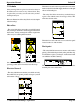
Operations Manual Polaris II 5.0 Operation This section covers the components of the laminator, the control panel, feed table, supply shaft, knife assembly film alignment and tension knobs. 5.1 Components on the laminator (1) POWER ON/ OFF: This is located to the lower right of the catch table. When set to the “I” position, applies power to the laminator. When set to the “O” position, removes power from the laminator. See Figure 5.1.1. Figure 5.1.
Polaris II (7) CATCH TABLE: The catch table is located at the rear of the machine and collects finished sheets. See Figure 5.1.3. Figure 5.1.3 Catch Table Operations Manual (9) AIR GAUGE & REGULATOR AND VACUUM GAUGE: The air pressure gauge and regulator indicate and control the amount of air being blown into the feeder stack. The vacuum gauge indicates how much suction is applied to the suction assembly. See Figure 5.1.5. Figure 5.1.
Operations Manual Polaris II (11) HEAT ROLLER SAFETY SHIELD: Reduces entanglement, entrapment and inadvertent contact with the heat rollers. See Figure 5.1.7. (14) FILM TENSION IDLER ROLLER: Located to the rear and next to the Teflon Heated Roller, it directs the film around to the Teflon Roller and has a brake to apply film tension to eliminate film wrinkles. See Figure 5.1.8. INFORMATION: The Heat Roller Safety Shield is designed to cover the heat roller while machine is running.
Polaris II Operations Manual (18) PAPER GUIDE PIN: The paper guide pin allows the operator to raise the finish product up to the knife separator for a smooth feed into the knife separator. See Figure 5.1.9. by the yellow hazard stickers and should be used to stop the machine in the event of an emergency. The emergency stop removes power from the machine. (23) NIP POINT: The point at which two rollers come into contact.
Operations Manual Polaris II 5.2 Control panel Refer to Figure 5.2.1 Control panel (1) START/SPEED UP: This button has a dual function. When the machine is stopped and all safety covers are closed, press and hold the START button to begin operation. The feeder head will cycle home while the START button is pressed. Once the feeder head is home, press the START button for 1 second. The nip roller will start to raise and after about 2 seconds, the laminator will start.
Polaris II Operations Manual Figure 5.2.
Operations Manual Polaris II (6) R: Reset Counter. This button resets the current job counter to 0. 5.3 Operator Screens The Touch screen has five operator screens. The following is a description of each screen: SPEED SCREEN 1 3 (8) SCREEN NAVIGATION: The arrow buttons move from one screen to the next. These buttons work the same on all of the operator screens.
Polaris II Operations Manual TEMPERATURE SCREEN 1 2 TE M P E R A TU R E TO P ON O N /O FF BOT OFF <--- ---> (2) PAPER WEIGHT: Use these buttons to select the nip pressure for the machine.Almost all paper stock can be run at HIGH pressure. If you experience wrinkles in the paper, stop the machine and select a lower pressure. You can not adjust the nip pressure while the machine is running.
Operations Manual alarm will activate and the laminator will stop. TOP HEAT SENSOR BLOCKED - When the top heat sensor is blocked for more than 5 seconds, this alarm will activate. When the alarm is displayed, the heat automatically shuts off and must be manually reset. BOTTOM HEAT SENSOR BLOCKED - When the bottom heat sensor is blocked for more than 5 seconds, this alarm will activate. When the alarm is displayed, the heat automatically shuts off and must be manually reset.
Polaris II Operations Manual Figure 5.7.
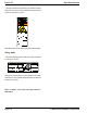
Operations Manual 6.0 Applications Polaris II Figure 6.1.1 Suction Cup Control O FF The Polaris will accommodate rolls of film on a 3 inch core. This section will describe how to load and thread film and start an application. This section will also give some helpful hints and important points to remember. ON WARNING: Do not wear ties, loose fitting clothes or dangling jewelry while operating or servicing the laminator.
Polaris II (9) The cutter On/Off indicator is to be off during the webbing process. Operations Manual Figure 6.1.3 Film Leader LEADER ATTACHED TO FILM WARNING: Roller are HOT. Use extreme caution when loading film. Direct contact with the rollers can burn you! (10) Lift the main roller safety shield for ease of webbing the film. (11) Pull the laminating film down under the rubber idler, and over the heat roller and allow film to drape down freely.
Operations Manual (22) After the second sheet passes through the nip, the automatic feed table will feed the nextsheet on the stack. As the secondsheet travels through the nip, it passes a paper sensor. When the paper passes the sensor, it allows the nextsheet to be laminated to enter the laminator. This feature allows the feeder to automatically set an overlap. (23) After a web of film and paper are running through the laminator, turn the knife on by pressing Cutter ON/ OFF.
Polaris II Operations Manual INFORMATION: Wrinkles may result if an attempt is made to reposition an item once it has entered the nip of the heat rollers. INFORMATION: When feeding long items, Skewing may occur if the item is not fed into the laminator straight. Use the feed guide and guide wheels to help prevent this from happening.
Operations Manual Polaris II Quick Setup Operation Tips 1. Place sheets in feeder with the grain parallel with the Nip. Feeding: - Keep the top of the pile 1/8” from the infeed plate by using wodden wedges. - Keep the front of the pile flat within 1/8”. - Place 10-15 sheets of scrap paper on top of the job for setup and start. - Place 1” of scrap paper under the job to insure all sheets are fed. - Supply only enough air to the paper stack to float sheets up to the infeed plate. 2.
Polaris II Operations Manual Application Guide The folloing chart is intended to be used as a guide to set up the machine for different applications. These are starting points for the setup process. Factors such as humitity and media/film qualtity can effect the final setting to obtain the best qualitiy. HiTac Films For Digital Printers Media 24lb Bond (75 gms) 80lb Cover (218 gms) 90lb Cover (244 gms) Top Roll Temp 290 Deg. F 290 Deg. F 290 Deg. F Machine Settings Bot.
Operations Manual Polaris II 7.0 Maintenance & Troubleshooting 7.1 Cabinets and cover General Binding Corporation laminators require minimal maintenance. However, regular maintenance is essential to keep any piece of precision machinery at peak performance. A maintenance schedule and a section of procedures are included in this section. ELECTRICAL HAZARD: Remove power from the laminator before cleaning. You can be severely shocked, killed or cause a fire.
Polaris II Operations Manual 1. Remove the film from the laminator. 7.4 Troubleshooting 2. Preheat the laminator to 240 deg. F. As an operator, you can perform some basic troubleshooting before contacting your local service representative. 3. Rub the top and bottom heat rollers with a clean, lint free cloth and mineral spirits. 4. Use the “Inching” funcion to rotate the heat rollers to a new area for cleaning. Continue this process until the complete surface of both rollers are clean.
Operations Manual Polaris II Figure 7.3.1 Troubleshooting guide Symptom Solution Laminator won’t run. Verify that unit is plugged in and power is present. Check control panel for machine status. Check fuses. Feed pile light must be on. Check pick up heads. Check suction at pick up heads. Check air blast. Check pile height proximity switch. Insure that paper is properly stacked and fanned. Check fuse. Verify sheet feed eye (1st eye) is clean.
Polaris II Page 7-4 Operations Manual © 2004 General Binding Corporation