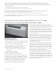
LEADERS IN EFFICIENCY GE ZONELINE® ARCHITECTS AND ENGINEERS DATA MANUAL GE Zoneline packaged terminal air conditioners
QUICK REFERENCE Full Specs on pages 54 and 55 ALL UNITS REQUIRE POWER CONNECTION KIT Power Connection Kit determines resistance heat output 7000 BTUH units are not offered with 4.7 KW resistance heater 4100 series cooling with electric heat MODEL NUMBER AZ41E07DAB AZ41E09DAB AZ41E12DAB AZ41E15DAB AZ41E07EAB AZ41E09EAB AZ41E12EAB AZ41E15EAB VOLTAGE COOLING (BTUH) EER WATTS 208 230 208 230 208 230 208 230 265 265 265 265 6900 7200 9600 9700 11500 11800 14000 14300 7200 9700 11800 14300 12.3 12.3 12.
QUICK REFERENCE Full Specs on pages 54 and 55 ALL UNITS REQUIRE POWER CONNECTION KIT Power Connection Kit determines resistance heat output 7000 BTUH units are not offered with 4.7 KW resistance heater 6100 series heat pump with backup electric heat MODEL NUMBER AZ61H07DAB AZ61H09DAB AZ61H12DAB AZ61H15DAB AZ61H07EAB AZ61H09EAB AZ61H12EAB AZ61H15EAB VOLTAGE COOLING (BTUH) 208 230 208 230 208 230 208 230 265 265 265 265 6900 7100 9100 9400 11600 11700 14200 14500 7000 9400 11700 14400 EER WATTS 13.0 13.
POWER CONNECTION KITS 230/208-Volt Line-Cord Connection Units 230/208-Volt Sub-Base and Direct-Connected Units Line Cord Kit Electric Heat BTUH Electric Heater Watts Electric Heat Amps Min. Circuit Protection (Amps) Sub-Base Direct Connection Kit Electric Heat BTUH Electric Heater Watts Electric Heat Amps Min. Circuit Protection (Amps) RAK3153A RAK3203A RAK3303A 8150/7900 11200/10900 16000/15450 2450/2360 3350/3230 4750/4580 11.0/11.6 15.1/16.0 21.2/22.
The Zoneline 4100 and 6100 Series have incorporated changes suggested by customers, along with enhancements by GE’s Technology Team and changes necessary to meet new UL and NEC requirements. “L” shaped condenser coil. Cross-flow blower across the product line for quieter operation. The “Partial Open Vent Air” feature was a specific request by a customer.
TABLE OF CONTENTS Front Cover 1 Mini Specs 4100 and 6100 Series 2–3 Mini Specs Power Connection Kits and Nomenclature 4 The 4100/6100 and Dry Air 25 5 Table of Contents 6 Introduction 7 ® The Zoneline System 8 Features and Benefits Features Table 9 Features and Benefits 10–12 Auxiliary Control Settings 13–14 Central Desk Control 15 Remote Thermostat Control 16–18 Heat Pumps and Energy Savings 19–20 Installation and Dimensions Application Comments 21 Case Dimensions 22 Wall Case
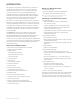
INTRODUCTION This manual is designed to provide product, performance and application information to our customers and their architects and engineers for use in selection and design of a zonal comfort control system utilizing GE Zoneline Packaged Terminal Air Conditioners (PTAC) and Packaged Terminal Heat Pumps (PTHP).
THE ZONELINE® SYSTEM The typical Zoneline installation consists of the wall case (or sleeve), chassis, power cord and exterior grille. Some installations may use a sub-base for support of the unit or for ease of electrical connections. Each of the components should be the standard products offered by GE, or, in the case of the exterior grille, approved by GE Applications Engineering.
ZONELINE FEATURES Resistance heat AZ 41 Series AZ 41 Dry Air 25 Heat pump AZ 61 Series Cooling EER range (230 Volts/265 Volts) 10.6 - 12.8 11.3 - 12.2 10.8 - 13.2 Heating COP range (230 Volts/265 Volts) N/A N/A 3.3 - 4.
FEATURES AND BENEFITS Standard Physical Dimensions Automatic Emergency Heat GE has maintained the same dimensions since 1961 — 42" wide x 16" high x 13-3/4" deep — making replacement of older units easy. Automatically uses electric resistance heat if the heat pump output is not sufficient to maintain selected room temperature.
FEATURES AND BENEFITS (cont) Fan-Only Setting – HIGH/LOW Indoor Coil Frost Control The unit provides the option of selecting either HIGH or LOW speed for Fan-Only operation. Prevents indoor coil from freezing and causing complaints due to lack of cooling. Frost can form on the indoor coil when the unit is operated in cooling when outdoor temperatures are low. The unit automatically shuts the compressor off until the indoor coil temperature warms to the point where frosting will no longer occur.
FEATURES AND BENEFITS (cont) Up-Front Air Filters Corrosion Protection (Optional) Two interchangeable up-front filters, easy to remove and reinstall, may be cleaned without opening or removing the room front. 4100 and 6100 Series units may be ordered with special protection to better withstand damage from salt air and salt water in seacoast or other corrosive areas. Clean filters by brushing, vacuuming or backflushing under faucet or shower head.
AUXILIARY CONTROL—AUX SET BUTTON The auxiliary control push button is located behind the room cabinet, below the control panel. The auxiliary controls come preset to the modes most desired by customers. However, the owner is responsible for ensuring the auxiliary controls are set to the desired function. There are 9 different modes that can be set using the auxiliary set button. Press “AUX SET” Press “Mode” Smart Fan Press HEAT COOL To change modes: • Press the STOP button.
AUXILIARY CONTROL SETTINGS (cont) Mode 3—Freeze Sentinel/Heat Sentinel The default settings for Mode 3 are: Heat Sentinel is off Freeze Sentinel is on. When Freeze Sentinel is activated, it automatically provides heat without user interface. This helps to prevent plumbing damage by turning the heater and indoor fan ON at 41ºF and OFF at 46ºF. When Heat Sentinel is activated, it automatically provides cooling without user interface.
CENTRAL DESK CONTROL Some installations may want to govern the ability of the unit to operate from a control device remote to the unit or even remote to the room in which the unit is located. The general term given to systems such as this is Central Desk Control (CDC). The most common installation of this type of system is a switch mounted at the registration desk and, upon guest check-in, a button is pushed or a switch is moved to allow the air conditioner to operate.
REMOTE THERMOSTAT CONTROL Resistance Heat Models The Zoneline 4100 resistance heat units may be connected to a single-stage thermostat designed for use with cooling with electric heat systems. GE offers two thermostats compatible with the 4100 Series unit. RAK164D2 — a solid-state digital thermostat requiring five connection wires. 16 RAK164P2 — a solid-state digital programmable thermostat requiring five connection wires.
REMOTE THERMOSTAT CONTROL (cont) Heat Pump Models Feature Heat Pump Electric Heat The Zoneline 6100 Series heat pump units may be connected to a single-stage cooling/two-stage heating thermostat designed for use with heat pump systems.
REMOTE THERMOSTAT CONTROL (cont) Remote Thermostat Control Selection Chart For Zoneline® Packaged Terminal Units Zoneline Series Thermostat Model 4100 RAK164D2 Digital RAK164P2 Digital Programmable RAK148D2 Digital RAK148P2 Digital Programmable 6100 Type Thermostat wire size – up to 60 feet AWG20 – up to 66 feet AWG18 For remote thermostat operation follow the steps below: 1. Turn on the unit and ensure it is working properly BEFORE proceeding. 2.
HEAT PUMPS AND ENERGY SAVINGS • GE Zoneline heat pumps are designed to provide cost-efficient heat pump operation while monitoring room conditions to maintain comfort. The units employ a logic system monitoring both outdoor and indoor temperatures to determine the heat source, thus increasing energy savings by operating longer in the heat pump mode. Heat pumps save energy and cost less to operate than units with electric resistance heaters as the only heat source.
HEAT PUMPS AND ENERGY SAVINGS (cont) Heat Pump Operation — Zoneline® 6100 Series Heat sources: Heat pump, heat pump and simultaneous electric resistance heat, or electric resistance heat. Zoneline heat pumps employ a highly featured microprocessor control system interfaced with thermistors to accurately measure indoor air temperature, outdoor air temperature, indoor coil temperature and outdoor coil temperature.
APPLICATION COMMENTS Use and Care Manual and installation instructions are shipped with Zoneline units. It is important that any air conditioning system be properly sized and applied in order to achieve the desired temperature and humidity levels in the space to be conditioned. Zoneline units are designed primarily to provide heating and cooling with the additional benefit that during operation in the cooling mode, the units also remove some moisture from the conditioned space.
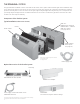
CASE DIMENSIONS RAB71A WALL CASE Additional Wall Case Depths RAB7116 - 16" RAB7124 - 24" RAB7128 - 28" RAB7131 - 31" 42" 1/2" SQ. HOLE (2 REQ'D.) A 13 4" 3/ 2-55/64" 1/4" DIA 1/2" 1-1/2" TYP 9-41/64" 16" 4" 8" WALL OPENING 16-1/4" MIN. x 42-1/4" MIN. 21" 1/2" DIA. HOLE (2 REQ'D.) 34" RAB77AA WALL CASE 42-1/8" 13-7/8" 2-7/8" 1-1/2" 1/2" SQ. HOLE (2 REQ'D.) 9/16" 16-1/4" 6" WALL OPENING 16-1/2" MIN. x 42-3/8" MIN. 1/2" DIA. (3 REQ'D.
WALL CASE A choice of wall cases is available for Zoneline® units. RAB71A — This insulated case is constructed of heavygauge galvanized steel and finished with a baked-enamel finish for protection and appearance. Design of the case provides for support of the chassis and free draining of any water entering the wall case. A petroleum microcrystalline wax is applied at critical points of fabrication to seal against moisture.
SUB-BASE (cont) RAK204D30P 208/230 volt 30-amp receptacle. Receptacle is NEMA6-30R with 18" of #12AWG wires attached to the receptacle. Short power connection kit included. Chaseway included. The junction box (RAK4002A for 4100 and 6100 Series units) that mounts on the chassis of 230/208 volt sub-base connected units must be purchased separately. Sub-bases for the 265-volt units: RAK204E15 265-volt 15-amp receptacle. Receptacle is NEMA7-15R with 18" of #12AWG wires attached to the receptacle.
WALL CASE INSTALLATION DATA (cont) MASONRY WALL CONSTRUCTION For new construction, early planning with the architect is necessary. Unit location, electrical connection locations and wall openings of the proper dimensions are essential to avoid the necessity of rework, fillers, framing, moving electrical outlets and other expensive modifications. For existing construction it is important that carpentry, masonry and electrical work be performed by competent, qualified personnel.
PREPARATION OF THE WALL CASE FOR ALL TYPES OF CONSTRUCTION Do not remove the stiffener from inside the wall case or the weather closure panel from the outside face of the wall case until the outdoor grille and chassis are ready to be installed. Installation of Wall Case in Wall Opening 1. Position the wall case into the wall.
JACK STUD FRAMING FOR WALL CASE HEADER – 4" x 4" OR 2 - 2" x 4" ON EDGE CRIPPLE Figure 1 SUB-FLOOR FINISHED FLOOR Note: Do not remove the stiffener support from inside the wall case until the chassis is to be installed. 16-1/4" MIN. RAB71A 16-1/2" MIN. RAB77A4 ADJUSTABLE FRAMING TO SECURE THIS DIMENSION 42-1/4" MIN. (RAB71A) 42-3/8" MIN. (RAB77A4) JACK STUDS MAIN STUD Brick Veneer and Frame Construction 2" MIN.
WALL RECEPTACLE (BY OTHERS) 2" MIN. CAULK* CAULK* OUTDOOR GRILLE POWER SUPPLY CONDUIT RAG60 1/4" RAG61, 62, 63 1-3/8" RAG67 1-1/4" 1/4" MIN. WALL CASE FINISHED FLOOR OR TOP OF CARPET 3" MIN. 5" MAX. Frame and Brick Veneer Installation STEEL LINTEL RAB71A 16" RAB77A4 16-1/4" MOUNTING SCREWS BY INSTALLER 20-7/8" (RAB71A) 21" (RAB77A4) RAB71A 13-3/4" RAB77A4 13-7/8" *Caulk around perimeter of wall case all four sides where it joins the building - Interior and Exterior.
USE NO SCREWS IN BOTTOM OF CASE OUTDOOR GRILLE Gasket and caulk around perimeter of wall case all four sides where it joins the building 16-1/4" MIN.
CAULK* D 2-1/2" ROOM CABINET See page 44 for line cord length. ELECTRICAL RECEPTACLE (BY OTHERS). FLUSH MOUNTED. D C CAULK* A CAULK* FRONT VIEW LINTEL ADJACENT WALL RAB71A 13-3/4" RAB77A4 13-7/8" *Caulk around perimeter of wall case all four sides where it joins the building - Interior and Exterior. TOP VIEW 27-1/4" ROOM CABINET CASE RAB71A 42" RAB77A4 42-1/8" WALL OPENING 16-1/4" x 42-1/4" MIN. FOR RAB71A 16-1/2" x 42-3/8" MIN.
METAL CASE EXTENSION FOR WALLS DEEPER THAN 13-1/8" (11-1/8" WITH SUB-BASE) 2" MIN. 1-1/2" (4 SIDES) 13-3/4" + D" FLASHING (FIELD SUPPLIED) RAB71A/77A4 WALL CASE SPLITTER BETWEEN AIR INTAKE AND DISCHARGE /8" -5 10 " /4 ±1 1" WIDE 45° DRIP LIP SEALANT - ALL FOUR (4) FLANGES FLANGES AND DRAIN HOLE LOCATIONS SAME AS ON WALL CASE 6-1/4" ± 1/4" CAULK* CAULK* ALL 4 SIDES RAB71A/77A4 CASE EXT.
A D A C B CAULK* CASE B 1" WIDE 45° DRIP LIP FLASHING OUTDOOR GRILLE DIMENSIONS: *Caulk around perimeter of wall case all four sides A. DISTANCE FROM GRILLE OR CASE TO OUTSIDE SURFACE OF WALL PLUS 2" TO 4" where it joins the building - Interior and Exterior. (TO INSERT UNDER CASE). B. 1" DRIP LIP (MINIMUM) C. 42" PLUS - SUFFICIENT TO FIT SNUGGLY UNDER AND UP AROUND THE CASE. D. 2" MINIMUM (CAUTION: WHEN CAULKING DO NOT BLOCK DRAIN HOLES IN CASE OR GRILLE.
7.70" 7.70" 13" SMALL 7/8" DIA. LARGE 1-1/8" DIA. D 7/8" LEVELING SCREW C CAULK* 3-11/16" LEVELING SCREWS (2) SUB-BASE BODY (2) SIDE EXTENSIONS FINISHED FLOOR B C A 2-3/8" MIN. CASE EDGE TO FINISHED WALL 13-3/4" CONDUIT ENTRY (ALTERNATES) SIDE VIEW MOUNTING SCREWS AND HOLES BY INSTALLER CAULK* 11-1/8" RAB71A 16" RAB77A4 16-1/4" CAULK* MAX. WALL THICKNESS *Caulk around perimeter of wall case all four sides where it joins the building - Interior and Exterior.
TYPE “B” SCREW 5/32" DIA. HOLE (SEE NOTE) FOR SECURING TYPE “D” CLIPS TO SLEEVE USING TYPE “A” SCREWS 6" TO SECURE SIDE CHANNELS TYPE “A” SCREW SCREW CLIP TYPE “D” TYPE “A” 2 REQ’D. TYPE “B” 8 REQ’D. TYPE “C” TYPE “E” TYPE “D” USE WITH RAB77A4 USE WITH RAB71A SUB-BASE MOUNTING CLIP TYPE “E” MOLDED CASE Electrical wiring may enter the sub-base through any of the knockout holes provided in the sub-base.
CONDENSATE DISPOSAL SYSTEMS Cooling Condensate Heat Pump Condensate Disposal Air conditioners produce condensate water as a result of lowering the humidity of the area being conditioned. When the indoor coil temperature is below the dew point, moisture in the air condenses into water droplets on the coil. This water drains to a pan located under the indoor coil and is routed through the barrier (the partition separating the indoor and outdoor sides of the unit) to the base pan on the outdoor side.
1/2" O.D. 90° ELBOW DRAIN TUBE SQUARE DRAIN HOLES SEE PAGE 37 NOTE #6 STEEL MOUNTING PLATE NEOPRENE SPONGE GASKET NOTE: Drain kit using either the 90° elbow tube or the straight tube may be installed without modification when using RAG60 exterior grille. Drain kit using the 90° elbow tube may be installed without modification when using RAG61 through RAG63 exterior grilles. Modification must be made to the RAG61 through RAG63 exterior grilles when using the straight tube.
COVER PLATE 1/2" OD TUBE GASKET CABINET BOTTOM OVERFLOW RELIEF DRAIN SEE NOTE 6 SQUARE DRAIN HOLES NEOPRENE SPONGE GASKET SEE DETAIL BELOW 1. The RAD10 drain kit is installed in the bottom of the wall case when it is desired to drain condensate to an internal drain system in the building. 2. The drain kit is mounted on the bottom of the wall case prior to installation of the case in the wall. It may be located anywhere on the room-side portion except for sub-base installations.
DUCTED INSTALLATIONS 4100 and 6100 Series Zoneline® units may be used in ducted installations. With a ducted installation it is possible to condition the air in two areas that have a common wall separating them. A special adapter mounts on the wall case and a transition piece directs the air from the unit into the adapter. Instructions for mounting the adapter to the wall case are included with the duct adapter.
Notes: 1. RAK6052 kit includes duct adapter, transition and mounting hardware. 2. RAK601 duct extension may be installed at either end of the RAK6052 duct adapter. Maximum duct extension length is 15'. Duct extension must be field fabricated for installations where length of duct exceeds length of RAK601 (44"). Field-fabricated duct extension must be insulated to prevent condensation from forming on exterior. Duct extension may not contain bends or turns. 3.
FINISHED FLOOR 16-1/8" 2-29/32" 7-3/32" ROOM CABINET TRANSITION WALL CASE 3/4" MIN. WALL TO CASE EDGE CAULK 12-3/4" MAX. *Caulk around perimeter of wall case all four sides where it joins the building - Interior and Exterior. RECEPTACLE CAULK* (BY OTHERS ALT. LOCATIONS) 10" RAK6052 ADAPTER 6-1/2" ANY CONSTRUCTION Line-Cord Installation RAG60 - 1/4" RAG61-63 - 1-3/8" RAG67 - 1-1/4" CAULK* CAULK 1/4" MIN. 3" MIN. 5" MAX.
EXTERIOR GRILLES Four styles of outdoor grilles are available for exterior treatments. The standard stamped aluminum grille (RAG60), the molded architectural louvered exterior grilles (RAG61-63) and the extruded aluminum architectural louvered grille (RAG67). All grilles include air deflectors (RAK40) and gaskets to prevent condenser air recirculation.
EXTERIOR ARCHITECTURAL TREATMENTS AND SPECIAL OUTDOOR GRILLES The architectural design of a building may dictate the use of special or oversized louvers for aesthetic reasons. Louvers other than standard Zoneline® exterior grilles may be used on the Zoneline unit, however, these special louvers, or any special exterior architectural treatments of the building facade that may restrict the free circulation of condenser airflow, should be referred to GE Application Engineering for evaluation and approval.
POWER CONNECTION FOR 4100 AND 6100 SERIES ZONELINE UNITS All 4100 and 6100 Series Zoneline units are equipped with universal heaters allowing chassis installation flexibility. The Zoneline units are connected to the building power supply by a unique power connection kit.
ESSENTIAL ELEMENTS ORDERING OVERVIEW 230/208-volt line-cord connected units — order line cord kit. 230/208-volt sub-base connected units — order sub-base (includes power connection kit) and junction box for chassis (if hard wired). 265-volt units — order sub-base and power connection kit separately. ELECTRICAL WIRING INFORMATION – 4100/6100 SERIES All Zonelines are single-phase 60 hertz units.
MAXIMUM CONNECTED LOAD The maximum connected load of a Zoneline unit occurs when the unit is in resistance heating operation. The maximum amperage shown in the tables below is the combined total of the resistance heater and the indoor fan motor.
NORMAL YEARLY OPERATING DATA (Cooling Hours based on 75°F indoor temperature with air conditioner sized to meet the design conditions.
OR A CN11 CN104 *2 *2 1 2 WH WH 5 BK TRANSFORMER 7 BK TERMINAL BOARD (265V) CN8 RY101 VARISTOR WH T1 RY102 BK CN110 4 R COMP. S RD RD BL NOTE: 1. *1:The lead wires are multicolured with black tube. *2:The jointwires are white except that the first one is red. *3:The 7k BTU models don't have this wire. 2.COLOR: BK:BLACK RE:RED GR:GREEN WH:WHITE GY:GRAY BL:BLUE BR:BROWN OR:ORANGE YL:YELLOW 3.THERMISTOR SENSOR RESISTANCE: AZ41E07DAB AZ41E07DAC AZ41E07DAP I.
TYPICAL 4100 SERIES, 230/208-VOLT SCHEMATIC DIAGRAM UNIVERSAL CONNECTOR *3 HEATER HEATER TERMINAL BOARD PROTECTOR COMP MOTOR FUSE O.L.P.
BR 1 3 O.D.COIL BCN301.BCN302 OUTDOOR BL BL BK OR OR BK 5 4 8 9 2 3 4 5 6 7 9 *3 *3 RY101 CN105(BK) RD 6 BL OR BK YL RD 1 3 OR (208/230V) 2 BL CN8 RV 1 OR (265V) BK 3 CN201(YL) YL I.D.COIL YL TERMINAL BOARD 1 ICR BCN7.BCN9 CN4.CN5.CN6 BK WH 7 YL TRANSFORMER BK RD 5 OPEATION BOARD UNIT 8 7 GR 2 *4 WH WH 6 GR WH WH *4 1 2 5 GY 1 BCN202 BR CN104 CN112 *2 4 BR GR *2 3 BR 6 2 1 YL RD *1 CN1 CN11 BCN106 FM I.D.
TYPICAL 6100 SERIES, 230/208-VOLT SCHEMATIC DIAGRAM UNIVERSAL CONNECTOR *3 HEATER RUNNING CAPACITOR HEATER 7. DC MO TERMINAL BOARD S R HEATER PROTECTOR COMP MOTOR CT101 TRIAC FUSE O.L.P. C Outdoor Fan Motor Indoor Fan Motor Reverse Valve Sol. ICR PUMP CN105 CN201 RY108 RY101 RY102 FU106 FU104 RY110 FU105 HEATER POWER CHECK CIRCUIT *1: C101 is used for 230V models and both C101A and C102 are used for 265V models *2:4A 250V is used for 230V models;3.15A 500V is used for 265Vmodels.
SUGGESTED BID FORM SPECIFICATIONS The following are suggested specifications for the Zoneline® 4100 Series Packaged Terminal Air Conditioner and the 6100 Series Packaged Terminal Heat Pump. The contractor will furnish Packaged Terminal Air Conditioners of the sizes and capacities shown on the schedule and in the specifications. The units shall be located as shown on the drawings and each shall consist of a chassis, room cabinet, wall case, sub-base if specified, and outdoor grille.
SUGGESTED BID FORM SPECIFICATIONS (cont) Heat pump unit shall include Reverse Cycle Defrost that automatically begins a defrost cycle when microprocessor determines criteria for defrosting has been met. Defrosting shall be accomplished by systematically ceasing heat pump operation, pausing to allow internal refrigerant pressures to equalize, then operating the compressor with the flow of refrigerant reversed to allow the hot gas to flow through the outdoor coil, melting the accumulated frost.
ZONELINE® CHASSIS NOMENCLATURE The Zoneline chassis is identified by a model number defining the type of unit, cooling capacity, electrical information and optional features included on the unit. When specifying or ordering the Zoneline chassis, use of this nomenclature will assure receiving the correct unit.
PRELIMINARY SPECIFICATIONS 4100 series cooling with electric heat 230/208V Models Capacity Cooling BTUH EER (BTU/Watt) Dehumidification Pts/Hr AZ41E07DAB AZ41E09DAB AZ41E12DAB AZ41E15DAB 7,200/6,900 12.3/12.3 1.7 9,700/9,600 12.0/12.0 2.7 11,800/11,500 11.1/11.1 3.5 14,300/14,000 10.3/10.3 4.6 R-410A 290 219 50/40 R-410A 340 229 70/45 R-410A 420 323 75/45 R-410A 409 324 75/45 89% 80% 580/560 2.8/3.0 19.0 89.2/102.5 93% 75% 805/795 3.6/3.9 21.0 100.0/113.0 93% 70% 1,060/1,035 4.7/5.1 29.5 99.
6100 series heat pump with backup electric heat 230/208V Models Capacity Cooling BTUH EER (BTU/Watt) Dehumidification Pts/Hr AZ61H07DAB AZ61H09DAB AZ61H12DAB AZ61H15DAB 7,100/6,900 13.0/13.0 1.7 9,400/9,100 12.2/12.2 2.7 11,700/11,600 11.6/11.6 3.5 14,500/14,200 10.6/10.6 4.5 R-410A 340 194 50/40 R-410A 360 212 70/45 R-410A 370 284 75/45 R-410A 370 290 75/45 91% 85% 545/525 2.6/2.8 19.0 6,200/6,100 3.9/3.9 465/445 2.2/2.4 94.1/107.1 92% 75% 755/740 3.5/3.8 21.0 8,300/8,100 3.7/3.7 650/635 3.
COMPLETE ACCESSORY LIST Kit Number Description RAA63 Spare Filters for AZ2900, AZ3900, AZ4100, AZ5800 and AZ6100 Series units For Additional Information Refer to Page 12 RAB71A Steel Wall Case – 13-3/4" deep 23 RAB7116 Steel Wall Case – 16" deep 23 RAB7124 Steel Wall Case – 24" deep 23 RAB7128 Steel Wall Case – 28" deep 23 RAB7131 Steel Wall Case – 31" deep 23 RAB77A4 Molded Wall Case 23 RAD10 Interior/Exterior Drain kit 36 RAF453A Room Front for A228, 29, 38, 39, 58, 41 & 61 seri
GENERAL INSTALLATION SUGGESTIONS Many times poor or non-existent caulking around the exterior of the wall case results in air infiltration, causing the unit to run excessively. One way to check for air infiltration is to look under and around the unit to the outdoors. If you can see light, there is air infiltration. The first floor of a building is where this problem most frequently occurs since caulking the bottom of the wall case may require lying outside in the dirt while working.
GENERAL INSTALLATION SUGGESTIONS (cont) Ducted Installation Comments New Installations The GE Zoneline® 4100 and 6100 Series are approved for ducted installation using the GE Duct Adapter model RAK6052 and the GE Duct Extension RAK601. A field-fabricated duct extension with the same interior measurements as the RAK601 may be used with the RAK6052 duct adapter. GE does not allow ducting in more than one direction.
ALPHABETICAL INDEX Category EXTERIOR GRILLE COLOR SAMPLES Page No.
GE APPLIANCES At GE, we’re reimagining home to introduce a new world of innovation in appliances. Today, we’re even more in sync with the consumer. Listening. Anticipating. Engineering ingenious ways to simplify life with more industry-first exclusives. We’re redefining style and functional design across all our products. Expanding our U.S. workforce and transforming manufacturing. Improving quality and efficiency.