
Built-In Dishwashers Installation Instructions
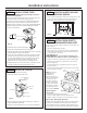

PREPARE HOT WATER SUPPLY
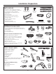
Hot Water Line
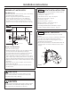
• The line may enter from either side, rear or floor within
the shaded area shown in Figure F.
• The line may pass through the same hole as the
electrical cable and drain hose, or an additional
1-1/2" diameter hole may be cut to accommodate
the water line. If a power cord with plug is used, the
water line must not pass through the power cord hole.
Water Line Connection
• Turn off the water supply.
• Install a hand shut-off valve in an accessible location,
such as under the sink. (Optional, but strongly
recommended and may be required by local codes.)
• The water connection is on the bottom left side
of the dishwasher. Install the hot water inlet line, using
3/8" or larger copper tubing. Route the line as shown in
Figure F and extend forward at least 19" from rear wall.
• Adjust the water heater to deliver water between 120°F
and 150°F.
• Flush water line to clean out debris. Use a bucket to
catch water and debris.
• The hot water supply line pressure must be between
20 and 120 PSI.
Installation Instructions
7
CAUTION
The hot water supply line pressure must be at least
20 PSI. Lower pressures could cause the water valve
to leak and cause water damage.
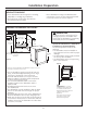
CAUTION
Do not remove wood base until you are ready to install
the dishwasher. The dishwasher will tip over when the
door is opened if the wood base is removed.
Figure F
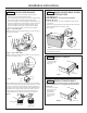
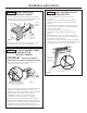
INSTALL TRIM PIECES
In this step, you will need the trim pieces set aside
in Step 1.
• Press top trim piece onto top of tub flange. Start with
the right edge and work your way to the left.
• Repeat process with the left and right trim pieces
working from the top down.
• Open and close the door to check that trim does not
bind and does not interfere with door latch or door
hinges.
STEP 2
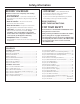
LOCATE INSTALLATION ITEMS
• Locate the items in the installation package and set
aside for use in the listed steps.
• Trim pieces – Step 2
• Junction box cover – Step 7 or Step 18
• Drain hose and clamp – Step 10
• Screw kit – Step 15
• Drain hose hanger – Step 17
• Owner’s Manual – Step 19 and Step 24
• Hard water test strip – Step 21
• Sound upgrade kit (selected models) – Step 22
• Product samples and/or coupons – Step 24
STEP 1
Figure G
2" From Floor
Shut-off
Valve
Hot
5"
5"
4"
4"
6"
19" From Wall
2"
From
Cabinet
1-1/2"
Dia.
Hole
Cabinet Face
Trim
Strip
Trim
Strip
Trim
Strip