CHIMNEY VENT HOODS SAFETY INFORMATION. . . . . . . . . . . . 3 USING THE HOOD Light Controls . . . . . . . . . . . . . . . . . . . . . . . . . . . 5 Vent Controls . . . . . . . . . . . . . . . . . . . . . . . . . . . 5 CARE AND CLEANING Grease Filter . . . . . . . . . . . . . . . . . . . . . . . . . . . . 6 Stainless Steel Surfaces . . . . . . . . . . . . . . . . . . . 7 LED Lights . . . . . . . . . . . . . . . . . . . . . . . . . . . . . .
THANK YOU FOR MAKING GE APPLIANCES A PART OF YOUR HOME. Whether you grew up with GE Appliances, or this is your first, we’re happy to have you in the family. We take pride in the craftsmanship, innovation and design that goes into every GE Appliances product, and we think you will too. Among other things, registration of your appliance ensures that we can deliver important product information and warranty details when you need them. Register your GE appliance now online.
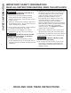
READ ALL INSTRUCTIONS BEFORE USING THE APPLIANCE WARNING TO REDUCE THE RISK OF FIRE, WARNING TO REDUCE THE RISK OF INJURY ELECTRIC SHOCK OR INJURY TO PERSONS, OBSERVE THE FOLLOWING: TO PERSONS IN THE EVENT OF A RANGE TOP GREASE FIRE, OBSERVE THE FOLLOWING*: A. Use this unit only in the manner intended by the manufacturer. If you have questions, contact the manufacturer. A. SMOTHER FLAMES with a close-fitting lid, cookie sheet or metal tray, then turn off the burner. BE CAREFUL TO PREVENT BURNS.
SAFETY INFORMATION IMPORTANT SAFETY INFORMATION READ ALL INSTRUCTIONS BEFORE USING THE APPLIANCE C. Clean ventilating fans frequently. Grease should not be allowed to accumulate on fan or filter. B. Sufficient air is needed for proper combustion and exhausting of gases through the flue (chimney) of fuel burning equipment to prevent back drafting.
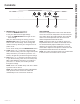
3 1. MEMORY/OFF: To set the memory: A. Press the MEMORY/OFF button. B. Set your desired fan and light settings. C. Press the MEMORY/OFF button again to save these settings. With your desired settings in memory, press the MEMORY/OFF button to restore the fan and light levels to their saved settings. These settings will remain in memory until they are changed or loss of power occurs. To turn off the hood, press the MEMORY/OFF button. 2.
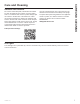
CARE AND CLEANING: Filters Filters Be sure electrical power is off and all surfaces are cool before cleaning or servicing any part of the vent hood. Metal Grease Filter The metal filter traps grease released by foods from the cooktop. The filter also helps prevent flames (from food, grease) from damaging the inside of the hood. For this reason, the filter must ALWAYS be in place when the hood is in use. The grease filter is dishwasher-safe and should be cleaned every 6 months, or as needed.
Stainless Steel Surfaces 'R QRW XVH D VWHHO ZRRO SDG LW ZLOO VFUDWFK WKH VXUIDFH To clean the stainless steel surface, use warm sudsy water or a stainless steel cleaner or polish. Always wipe the surface in the direction of the brush line. Follow the cleaner instructions for cleaning the stainless steel surface. Cleaners with oxalic acid such as Bar Keepers Friend Soft Cleanser™ will remove surface rust, tarnish, and small blemishes. To receive a $2.
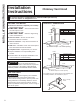
INSTALLATION INSTRUCTIONS Installation Instructions Chimney Vent Hood If you have questions, call GE Appliances at 800.GE.CARES (800.432.2737) or visit our website at: GEAppliances.com BEFORE YOU BEGIN PRODUCT DIMENSIONS Read these instructions completely and carefully. Ŷ 10-7 ´ IMPORTANT – Save these instructions for local inspector’s use.
PREPARE TO INSTALL THE HOOD INSTALLATION CLEARANCES ADVANCE PLANNING These vent hoods are designed to be installed onto a wall. They may be installed beneath a soffit or cabinet. Duct Install Planning Ŷ This hood is designed to be vented vertically through the ceiling. A duct transition piece is supplied for vertical exhaust. Use locally supplied elbows to vent horizontally through the rear wall. Ŷ Use metal ductwork only. Ŷ Determine the exact location of the vent hood.
INSTALLATION INSTRUCTIONS Installation Preparation POWER SUPPLY IMPORTANT—(Please read carefully) WARNING FOR PERSONAL SAFETY, THIS APPLIANCE MUST BE PROPERLY GROUNDED. Remove house fuse or open circuit breaker before beginning installation. Do not use an extension cord or adapter plug with this appliance. Follow National Electrical Codes or prevailing local codes and ordinances.
TOOLS AND MATERIALS REQUIRED (NOT SUPPLIED) REMOVE THE PACKAGING CAUTION Wear gloves to protect against sharp edges. Ŷ 5HPRYH WKH GXFW FRYHUV Safety glasses Ŷ 5HPRYH WKH KDUGZDUH EDJ OLWHUDWXUH SDFNDJH DQG other boxed parts. Pencil and tape measure Ŷ 5HPRYH DQG SURSHUO\ GLVFDUG WKH SURWHFWLYH plastic wrapping and other packaging materials.
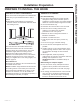
INSTALLATION INSTRUCTIONS Installation Preparation CHECK INSTALLATION HARDWARE Locate the hardware package packed with the hood and check contents. HARDWARE PACKAGE Locate and count screws Stainless steel filter GXFW FRYHU DQG air deflector screws WKUHDG IRUPLQJ 4 wall fasteners VFUHZ ´ ORQJ ´ VFUHZ with wall anchor) 6 wood screws ´ ORQJ WALL VENT IS 27-3/4" MIN.
INSTALLATION CLEARANCES PV970, PV976 These vent hoods are designed to be installed onto a wall with no above cabinets. Ŷ ,QVWDOO WKHVH KRRGV EHWZHHQ WKH UHTXLUHG ´ minimum and 36” recommended maximum above the cooking surface. 24” Required Min. 36” Recommended Max. 36” Typical The vent hood must be installed between the required 24” minimum and 36” recommended maximum above the cooking surface.
INSTALLATION INSTRUCTIONS Installation Instructions INSTALLATION - VENTED TO THE OUTSIDE DUCTWORK, WIRING LOCATIONS Ŷ Determine the exact location of the vent hood. Ŷ Locate the template packed with the literature. - Measure from the floor to the top of the cooking surface. Add hood installation height determined RQ SDJHV DQG 0DUN WKDW ORFDWLRQ - Use a level to draw a straight pencil line on the wall. - Tape the template in position along the penciled line. CHECK TO BE SURE THE TEMPLATE IS LEVEL.
INSTALLATION - VENTED TO THE OUTSIDE (Cont.) STEP 2: INSTALL HOOD MOUNTING SCREWS The two upper mounting screws must enter the horizontal support or wall studs. Ŷ :LWK WKH WHPSODWH WDSHG LQ SODFH XVH D SXQFK WR mark mounting bracket screw locations. Ŷ 'ULOO ´ SLORW KROHV LQ RI WKH SXQFKHG ORFDWLRQV in the lower bracket. If the bottom 2 pilot holes GR QRW HQWHU ZRRG HQODUJH WKH KROHV WR ´ DQG install metal wall fastener anchors (provided). Ŷ 5HPRYH WKH WHPSODWH WALL VENT IS 27-3/4" MIN.
INSTALLATION INSTRUCTIONS Installation Instructions INSTALLATION - VENTED TO THE OUTSIDE (Cont.) STEP 5: CONNECT DUCTWORK Ŷ Remove shipping tape from the damper. STEP 6: CONNECT ELECTRICAL (cont.) Ŷ Install ductwork, making connections in the direction of airflow as illustrated. Ŷ 6HFXUH WKH KRXVH ZLULQJ WR WKH MXQFWLRQ ER[ ZLWK a strain relief (not provided). Ŷ Push duct over the exhaust outlet and damper. Ŷ Secure joints in ductwork with sheet metal screws.
INSTALLATION - VENTED TO THE OUTSIDE (Cont.) STEP 7: INSTALL DUCT COVERS Ŷ 5HPRYH SURWHFWLYH SODVWLF covering. Ŷ $VVHPEOH GXFW FRYHUV according to application. Mounting screws STEP 8: INSTALL METAL GREASE FILTER Ŷ 5HPRYH WKH SURWHFWLYH ILOP RQ WKH JUHDVH ILOWHU NOTE: The charcoal filter is not required for this installation. NOTE: The inside duct cover has vent holes on one end. The holes are intended for use when the hood is installed for recirculating purposes.
INSTALLATION INSTRUCTIONS Installation Instructions INSTALLATION - RECIRCULATING DUCTWORK, WIRING LOCATIONS Ŷ 'HWHUPLQH WKH H[DFW ORFDWLRQ RI WKH YHQW KRRG Ŷ /RFDWH WKH WHPSODWH SDFNHG ZLWK WKH OLWHUDWXUH Ŷ 0HDVXUH IURP WKH IORRU WR WKH WRS RI WKH FRRNLQJ surface. Add hood installation height determined RQ SDJHV DQG 0DUN WKDW ORFDWLRQ STEP 1: INSTALL FRAMING FOR HOOD SUPPORT IMPORTANT: Framing must be capable of supporting 100 lbs. Ŷ 7DSH WKH WHPSODWH LQ SRVLWLRQ DORQJ WKH SHQFLOHG line.
INSTALLATION - RECIRCULATING (Cont.) STEP 2: INSTALL HOOD MOUNTING SCREWS STEP 3: INSTALL DUCT BRACKET AND DEFLECTOR The mounting screws must enter the horizontal support or wall studs. The duct bracket should be installed against the EDFN ZDOO DQG IOXVK ZLWK WKH FHLOLQJ WKH SRLQW where the ceiling meets the wall should be level for the bracket and duct cover to fit flush. This bracket will hold the duct cover in place at the top.
INSTALLATION INSTRUCTIONS Installation Instructions INSTALLATION - RECIRCULATING (Cont.) STEP 4: MOUNT THE HOOD WARNING 2 people are required to lift and position the hood onto the mounting screws. Ŷ Lift the hood onto the mounting screws. Ŷ ,I XVLQJ D ZDOO IDVWHQHU PDNH VXUH WKH ZDVKHU LV in front of the flange and not behind it. Check with a level before tightening screws. STEP 5: SIZE AND CUT DUCT PIECE Ŷ Measure from the bottom of the air deflector to the top of the hood as shown.
INSTALLATION - RECIRCULATING (Cont.) STEP 6: CONNECT ELECTRICAL STEP 7: INSTALL DUCT COVERS Verify that power is turned off at the source. Ŷ Remove protective plastic Mounting screws covering. Ŷ Assemble duct covers according to application. NOTE: The upper duct cover has Vent holes vent holes on one end intended for use when the hood is installed for recirculating purposes. Be VXUH WKH YHQWHG HQG LV DW WKH WRS the vent holes will be visible in this installation.
INSTALLATION INSTRUCTIONS Installation Instructions INSTALLATION - RECIRCULATING (Cont.) STEP 8: INSTALL FILTERS STEP 9: FINALIZE INSTALLATION Charcoal Filter Ŷ Remove all tape and packaging materials. Insert the charcoal filter into the opening. Push the latch on both sides toward the center and engage the flange. Ŷ 5HIHU WR WKH 2SHUDWLQJ ,QVWUXFWLRQV LQ WKLV manual to operate the hood.
Save time and money! Review the charts on the following pages first and you may not need to call for service. Problem Possible Cause What To Do Fan/Light does not operate when either button is pressed A house fuse may be blown or a circuit breaker tripped. Replace fuse or reset circuit breaker. Fan does not operate when fan + or – buttonsor MEMORY/OFF button is pressed The blower connector is loose or not plugged into its mating connector. Disconnect power to the unit.
Notes 24 49-2000916 Rev.
GEAppliances.com All warranty service is provided by our Factory Service Centers, or an authorized Customer Care® technician. To schedule service online, visit us at geappliances.com/service RU FDOO *( $SSOLDQFHV DW *( &$5(6 3OHDVH have your serial number and your model number available when calling for service. Servicing your appliance may require the use of the onboard data port for diagnostics.
CONSUMER SUPPORT Consumer Support GE Appliances Website Have a question or need assistance with your appliance? Try the GE Appliances Website 24 hours a day, any day of the year! You can also shop for more great GE Appliances products and take advantage of all our on-line support services designed for your convenience. In the US: GEAppliances.
CAMPANAS DE VENTILACIÓN DE CHIMENEA INSTRUCCIONES DE SEGURIDAD. . . . . . . . . . . . . . . . . . . . 3 USO DE LA CAMPANA Controles de la luz . . . . . . . . . . . . . . . . . . . . . . . 5 Controles de la ventilación . . . . . . . . . . . . . . . . 5 CUIDADO Y LIMPIEZA MANUAL DEL PROPIETARIO Y INSTALACIÓN PV970 PV976 Filtro de grasa . . . . . . . . . . . . . . . . . . . . . . . . . . . 6 Superficies de acero inoxidable . . . . . . . . . . . . 7 Luces LED . . . . . . . . . . . . . . . . . . . . . . .
GRACIAS POR HACER QUE GE APPLIANCES SEA PARTE DE SU HOGAR. Ya sea que haya crecido usando GE Appliances, o que ésta es su primera vez, nos complace tenerlo en la familia. Sentimos orgullo por el nivel de arte, innovación y diseño de cada uno de los electrodomésticos de GE Appliances, y creemos que usted también. Entre otras cosas, el registro de su electrodoméstico asegura que podamos entregarle información importante del producto y detalles de la garantía cuando los necesite.
ADVERTENCIA PARA REDUCIR EL RIESGO DE INCENDIO, DESCARGA ELÉCTRICA O LESIONES A PERSONAS, CUMPLA CON LOS SIGUIENTES PUNTOS: A. Utilice esta unidad sólo de la manera concebida por el fabricante. Si tiene alguna pregunta, comuníquese con el fabricante. B. Antes de realizar reparaciones o limpiar la unidad, desconecte la energía del panel de servicio y bloquee los medios de desconexión para evitar el accionamiento de la energía de manera accidental.
INFORMACIÓN DE SEGURIDAD INFORMACIÓN IMPORTANTE DE SEGURIDAD LEA TODAS LAS INSTRUCCIONES ANTES DE USAR ADVERTENCIA PARA REDUCIR EL RIESGO DE UN INCENDIO DE GRASA SOBRE UNA ESTUFA: A. Nunca deje unidades de superficie desatendidas en configuraciones de calor elevadas. Los alimentos que hierven y se derraman provocan humo y derrames grasosos que pueden prenderse fuego. Caliente los aceites lentamente en configuraciones bajas o medias. B.
3 1. MEMORY/OFF (memoria/apagado) Para configurar la memoria: A. Presione el botón MEMORY/OFF. B. Ingrese las configuraciones deseadas de ventilación y de luz. C. Presione el botón MEMORY/OFF de nuevo para guardar estas configuraciones. Con sus configuraciones deseadas en la memoria, presione el botón MEMORY/OFF para restablecer los niveles de ventilación y de luz a sus configuraciones guardadas. Estas configuraciones permanecerán en la memoria hasta que se modifiquen u ocurra un corte de energía.s.
CUIDADO Y LIMPIEZA: Filtros Filtros Asegúrese de que el disyuntor esté apagado y que todas las superficies estén frías antes de limpiar o de realizar el servicio técnico de cualquier pieza de la campana de ventilación. Filtro de grasa metálico El filtro metálico atrapa la grasa liberada por los alimentos desde la estufa. El filtro también ayuda a evitar que las llamas (de los alimentos, grasa) dañen la parte interna de la campana.
Superficies de acero inoxidable No utilice almohadillas de acero porque rayan la superficie. Para limpiar la superficie de acero inoxidable, utilice agua tibia jabonosa o un limpiador o lustrador de acero inoxidable. Siempre limpie la superficie en dirección de la veta. Siga las instrucciones del producto para limpiar la superficie de acero inoxidable. Los limpiadores con ácido oxálico tales como Bar Keepers Friend Soft Cleanser™ eliminarán el óxido sobre la superficie, deslustres y pequeñas manchas.
INSTRUCCIONES DE INSTALACIÓN Instrucciones de instalación Campanas de ventilación de chimenea ¿Preguntas? Llame al 800.GE.CARES (800.432.2737) o visite nuestro sitio Web en: GEAppliances.com ANTES DE COMENZAR DIMENSIONES DEL PRODUCTO Lea estas instrucciones por completo y con detenimiento. Ŷ 10-7 ´ IMPORTANTE – Guarde estas instrucciones para el uso de inspectores locales. Ŷ *Altura hasta el cielorraso IMPORTANTE – Cumpla con todos los códigos y ordenanzas vigentes.
PREPARACIÓN PARA INSTALAR LA CAMPANA ESPACIO DE INSTALACIÓN PLANIFICACIÓN PREVIA Estas campanas de ventilación están diseñadas para instalarse sobre una pared. Pueden instalarse debajo de un sofito o gabinete. Planificación para la Instalación con Conducto Ŷ Determine la ubicación exacta de la campana de ventilación. Ŷ Utilice sólo conductos de metal rígidos. Ŷ Planifique el recorrido de la salida de ventilación hacia el exterior.
INSTRUCCIONES DE INSTALACIÓN Preparación para la instalación SUMINISTRO DE ENERGÍA IMPORTANTE – (Tenga a bien leer cuidadosamente) ADVERTENCIA PARA SEGURIDAD PERSONAL, ESTE APARATO DEBE CONECTARSE A TIERRA DE MANERA ADECUADA. Quite el fusible o abra el interruptor de circuitos antes de comenzar la instalación. No utilice un cable de extensión o un enchufe adaptador con este artefacto. Siga los Códigos Eléctricos Nacionales o códigos y ordenanzas locales vigentes.
HERRAMIENTAS Y MATERIALES REQUERIDOS (NO SUMINISTRADOS) QUITE EL ENVOLTORIO PRECAUCIÓN Se guantes para protegerse de los bordes afilados. Ŷ 4XLWH ODV FXELHUWDV GH ORV FRQGXFWRV Gafas de seguridad Lápiz y cinta métrica Ŷ 4XLWH OD EROVD GH SLH]DV HO SDTXHWH GH LQVWUXFFLRQHV \ otras piezas en cajas. Ŷ 4XLWH \ GHVFDUWH DGHFXDGDPHQWH HO HQYROWRULR SOiVWLFR de protección y otros materiales de empaque.
INSTRUCCIONES DE INSTALACIÓN Preparación para la instalación CONTROLE LAS PIEZAS DE INSTALACIÓN Ubique el paquete de hardware embalado con la campana y verifique los contenidos.. PAQUETE DE HARDWARE Ubique y cuente los tornillos Filtro de acero inoxidable 4 sujeciones GH SDUHG ´ (Tornillo con anclajes de pared) 6 tornillos para madera 1 GH ´ de longitud) WALL VENT IS 27-3/4" MIN.
ESPACIO DE INSTALACIÓN Estas campanas de ventilación están diseñadas para ser instaladas en una pared sin gabinetes superiores. Ŷ ,QVWDOH HVWDV FDPSDQDV HQWUH HO PtQLPR UHTXHULGR de 24” y el máximo recomendado de 36” sobre la superficie de cocción. 24” Requeridos Mín. 36” Recomendado Max. 36” Típico La campana de ventilación debe ser instalada entre el mínimo requerido de 24” y el máximo recomendado de 36” sobre la superficie de cocción.
INSTRUCCIONES DE INSTALACIÓN Instrucciones de Instalación INSTALACIÓN - VENTILACIÓN HACIA EL EXTERIOR UBICACIONES DE LOS CONDUCTOS Y CABLEADO Ŷ Determine la ubicación exacta de la campana de ventilación. IMPORTANTE: El armazón debe poder soportar 100 lbs. Ŷ Ubique la plantilla embalada con las instrucciones. - Mida desde el piso hasta el extremo superior de la superficie de cocción. Agregue la altura de instalación de la campana determinada en las SiJLQDV \ 0DUTXH HVD XELFDFLyQ - Utilice un nivel
INSTALACIÓN - VENTILACIÓN HACIA EL EXTERIOR (Cont.) PASO 2: INSTALE LOS TORNILLOS DE MONTAJE DE LA CAMPANA Los dos tornillos de montaje superiores deben ingresar en el soporte horizontal o en las columnas de pared. Ŷ &RQ OD SODQWLOOD DGKHULGD FRQ FLQWD HQ VX OXJDU XWLOLFH una perforadora para marcar las ubicaciones de los tornillos del soporte de montaje. Ŷ 3HUIRUH RULILFLRV SLORWR GH ´ HQ GH ODV XELFDFLRQHV perforadas en el soporte inferior.
INSTRUCCIONES DE INSTALACIÓN Instrucciones de instalación INSTALACIÓN - VENTILACIÓN HACIA EL EXTERIOR (Cont.) PASO 5: CONECTE LOS CONDUCTOS Ŷ Quite la cinta de embalaje del regulador de tiro. Ŷ Instale el conducto, realizando conexiones en la dirección del flujo de aire, como se ilustra. Ŷ Presione el conducto sobre la salida de escape y el regulador de tiro. PASO 6: CONECTE LOS ELEMENTOS ELÉCTRICOS (cont.) Ŷ $VHJXUH HO FDEOHDGR GRPpVWLFR D OD FDMD de conexiones con un alivio de tensión (no provisto).
INSTALACIÓN - VENTILACIÓN HACIA EL EXTERIOR (Cont.) PASO 7: INSTALE LAS CUBIERTAS DEL CONDUCTO PASO 8: INSTALE EL FILTRO DE GRASA METÁLICO Ŷ 4XLWH OD WDSD SURWHFWRUD de plástico. Ŷ 4XLWH OD SHOtFXOD SURWHFWRUD GHO ILOWUR GH JUDVD NOTA: No se necesita el filtro de carbón para esta instalación. Ŷ $UPH ODV FXELHUWDV GHO conducto de acuerdo con la aplicación. Tornillos de montaje NOTA: La cubierta del conducto interior cuenta con orificios de ventilación en un extremo.
INSTRUCCIONES DE INSTALACIÓN Instrucciones de instalación INSTALACIÓN - RECIRCULACIÓN UBICACIONES DE LOS CONDUCTOS Y CABLEADO Ŷ 'HWHUPLQH OD XELFDFLyQ H[DFWD GH OD FDPSDQD de ventilación. PASO 1: INSTALE EL ARMAZÓN PARA EL SOPORTE DE LA CAMPANA IMPORTANTE: El armazón debe poder soportar 100 lbs. Ŷ 8ELTXH OD SODQWLOOD HPSDFDGD FRQ ODV LQVWUXFFLRQHV Ŷ 0LGD GHVGH HO SLVR KDVWD HO H[WUHPR VXSHULRU de la superficie de cocción. Agregue la altura de instalación de la campana determinada en las SiJLQDV \
INSTALACIÓN - RECIRCULACIÓN (Cont.) PASO 2: INSTALE LOS TORNILLOS DE MONTAJE DE LA CAMPANA PASO 3: INSTALE EL SOPORTE DEL CONDUCTO Y EL DEFLECTOR Los tornillos de montaje deben ingresar en el soporte horizontal o en las columnas de pared. El soporte del conducto debe instalarse contra la pared WUDVHUD HQ IRUPD DOLQHDGD FRQ HO FLHORUUDVR HO SXQWR donde el cielorraso se une con la pared debe estar nivelado para que el soporte y la cubierta del conducto queden alineados.
INSTRUCCIONES DE INSTALACIÓN Instrucciones de instalación INSTALACIÓN - RECIRCULACIÓN (Cont.) PASO 4: INSTALE LA CAMPANA ADVERTENCIA Se necesitan 2 personas para levantar y colocar la campana sobre los tornillos de montaje. Ŷ Levante la campana y colóquela sobre los tornillos de montaje. Ŷ 6L XWLOL]D XQD VXMHFLyQ GH SDUHG YHULILTXH TXH ODV arandelas estén adelante de la brida y no detrás. Controle con un nivel antes de ajustar los tornillos.
INSTALACIÓN - RECIRCULACIÓN (Cont.) PASO 6: CONECTE LOS ELEMENTOS ELÉCTRICOS PASO 7: INSTALE LAS CUBIERTAS DEL CONDUCTO Verifique que la energía esté cortada en la fuente. Ŷ Quite la tapa protectora de plástico. Tornillos de montaje Ŷ Arme las cubiertas del conducto de acuerdo con la aplicación. NOTA: La cubierta del conducto superior cuenta con orificios Orificios de de ventilación en un extremo ventilación previstos para ser usados cuando se instala la campana para efectuar una recirculación.
INSTRUCCIONES DE INSTALACIÓN Instrucciones de instalación INSTALACIÓN - RECIRCULACIÓN (Cont.) PASO 8: INSTALE LOS FILTROS PASO 9: FINALICE LA INSTALACIÓN Filtro de carbón Ŷ Quite toda la cinta y material de empaque. Introduzca el filtro de carbón dentro de la abertura. Presione la traba sobre ambos lados hacia el centro y sujete la brida. Ŷ &RQVXOWH ODV ,QVWUXFFLRQHV GH RSHUDFLyQ GH HVWH manual para operar la campana.
¡Ahorre tiempo y dinero! Primero revise los cuadros que aparecen en las siguientes páginas y es posible que no necesite solicitar reparaciones. Problema Causas posibles Qué hacer El ventilador/la luz no funcionan cuando se presionan los botones El fusible puede haberse quemado o el interruptor de circuitos puede haber saltado. Cambie los fusibles o reconfigure el interruptor de circuitos.
Notas 24 49-2000916 Rev.
GEAppliances.com Todo el servicio de garantía es provisto por nuestros Centros de Servicio de Fabricación, o un técnico autorizado de Customer Care®. Para programar una visita del servicio técnico a través de Internet, visítenos en geappliances.com/service R OODPH DO *( &$5(6 &XDQGR OODPH SDUD VROLFLWDU HO VHUYLFLR WHQJD ORV Q~PHURV GH VHULH \ PRGHOR GLVSRQLEOHV Para realizar el servicio técnico de su electrodoméstico, se podrá requerir el uso de datos del puerto de abordaje para su
SOPORTE PARA EL CONSUMIDOR Soporte para el Consumidor Sitio Web de GE Appliances ¿Desea realizar una consulta o necesita ayuda con su electrodoméstico? ¡Intente a través del Sitio Web de GE Appliances las 24 horas del día, cualquier día del año! Usted también puede comprar más electrodomésticos maravillosos de GE Appliances y aprovechar todos nuestros servicios de soporte a través de Internet, diseñados para su conveniencia. En EE.UU.: GEAppliances.