
Use and Care Guide
These issues develop when the combination of high operating
frequency and parasitic capacitance from the wiring create
unintended coupling between conductors or to earth ground.
Each wire in the fixture and the interconnect whip will have a
certain capacitance to other wires running parallel to it, and also a
capacitance to earth ground. This unintended capacitive coupling
creates a shunt path taking away some energy that was intended for
the lamp load. This causes reductions in the available open circuit
voltage need to strike the lamp or a loss of preheating energy. Both
cases lead to poor or erratic starting in the remote fixture(s).
For some multiple lamp ballasts, certain lamp leads are at higher
potential and should be connected to lamps that reside in the same
fixture as the ballast. The ballast manufacturer may have specific
recommendations as to which of the lamp leads can be utilized for
the remote fixture of a tandem set, and restrictions on how long the
wiring from ballast to lamp may be. Ballasts may also have different
permissible wiring lengths per lamp lead color based on the applica-
tion. Remote mounting applications may permit a longer wiring length
than some tandem applications as the remote situation presents a
uniform loss to all lamp leads. The tandem operation scheme may
present different capacitances to different lamp leads that could
result in poor starting and differences in light level during operation.
In some cases, these issues are compounded because the intercon-
nect whip is carrying wires connected to two different ballasts.
Since the ballasts are not likely to be exactly in phase, there can be
additional losses due to capacitive phase cancellation between leads
of the two different ballasts. There may also be system interactions
where either ballast will work fine separately, but will not work
together. In these cases, the interconnect whip may need to be
shorter, limiting the distance between the fixtures, or two separate
whips could be used.
As the ballast operating frequency gets higher, the capacitive
shunting effect become more pronounced. Dimming ballasts typically
are at the highest frequency when in deep dimming. Due to the
effects of capacitive losses, lamps may appear at different intensities
or drop out and may flicker due to losses of cathode heating energy.
It is recommended that dimming ballasts not be remote mounted or
used in tandem operation, all lamp wiring must stay within the fixture
containing the dimming ballast.
Energy saving lamps may be more susceptible to starting issues when
used in remote or tandem fixture operation. These lamps utilize a gas
mixture that does not ionize as easily as full wattage lamps, and are
more likely to have starting issues due to the reduced starting voltage
resulting from the capacitive losses.
Remote starting distances are specified at room temperature using
standard life, full wattage lamps, with one ballast driving all lamps
located in the remote fixture through a single conduit at the specified
distance. In view of the possible differences related to any specific
application, it is advised that any tandem or remote mount application
using one or more ballasts be tested in the final configuration to ensure
the system will perform as expected in the intended environment.
As ballasts decrease in size, the operation frequency increases. The
increased frequency of operation makes capacitive effects more
pronounced. Capacitive effects come from a high frequency lead wire
being in proximity to another lead wire or the grounded metal of the
fixture. Worse capacitive effects result when the lead wires are closer
and the frequency is higher.
When installing ballasts into fixtures, the wiring needs to be routed
point to point and if possible, the excess wire trimmed out. Occasion-
ally, some installers tend to be too neat, twisting the wires together or
bundling the wires together with wire ties. While this does make for a
neat fixture, it may create capacitive effect issues for the lamp and
ballast system.
Wire bundling can create unintended current flows from lead to lead
and also from lead to ground in the fixture. These current flows are
parasitic, and will reduce the available starting voltage, preheating
current or discharge current in the lamp. The results can be poor or
erratic starting or reduced system efficacy as some of the energy
from the ballast is getting “short circuited” away from the intended
lamp load. In T5 or CFL applications, excessive stray capacitance can
also affect End Of Life circuit operation, causing the ballast to
prematurely shut down.
In dual switched systems, or systems that use two or more ballasts
within the same fixture, ballasts more subject to cross talk and
interference due to capacitive effects. It is important the wiring be
placed neatly without bunching up the excess in the wiring channel.
Lamp leads can run parallel to each other but should not be bundled
or tied together. Lamp leads should also trimmed when possible to
eliminate excess lead length. It is also good to keep the output leads
from one ballast away from those of the other ballast. Lamp leads
should also be kept away from the AC input leads as this can cause
undesired interference or EMI, which can affect other devices
operating on the same power source.
In summary, the lamp lead wiring should be laid parallel into the
fixture with excess length trimmed. Do not twist or otherwise bundle
the leads together, and ensure no leads are caught or crimped
between the ballast channel cover and the fixture body.
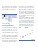
Remote and Tandem Mounting of Ballasts
As today’s economics drive lower first costs, many fixture manufac-
turers increasingly use only one ballast to operate lamps in two or
more fixtures. This tandem mounting scheme decreases the total
number of ballasts needed for a given installation. The fixtures are
typically interconnected with a wiring “whip” of flexible metal conduit
with a number of wires inside. The whip brings the high frequency
lamp leads from the ballast in one fixture to the lamp or lamps in a
satellite fixture. Tandem operation has lamps operating in the fixture
that has the ballast and also in the satellite fixture.
Remote mounting is when a ballast is located in a separate enclosure
without lamps and wires to all the lamps run through a conduit or
flexible whip to a remote fixture which contains the lamps.
In past years, ballasts were magnetic and operated at 60 Hz, and
tandem or remote mounting scheme was only occasionally used,
so issues with remote or tandem mounting were not so frequent.
In today’s energy efficient electronic ballasts, the frequency is much
higher, usually greater than 40 kHz, and more fixtures are being
tandem operated to manage first costs of a system. Tandem
operation can lead to system issues such as poor or erratic starting
and differences in light level during steady state lamp operation.