User Manual 1.32 m (52 in.) Selena Lighted Ceiling Fan MODELS: 20390 & 20406 120V 60Hz, MADE IN CHINA Customer Assistance 1-866-885-4649 r re Service Team at 1-866-885-4649 re 9:00AM-5:00PM EST -Monday-Friday Note: Installation videos for fans with GE Powerplug quick connection technology can be viewed and downloaded on www.gelightingandfans.
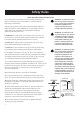
Safety Rules READ AND SAVE THESE INSTRUCTIONS WARNING: To reduce the risk of 1. To reduce the risk of electric shock, ensure electricity has fire, electric shock or personal been turned off at the circuit breaker or fuse box before injury, mount fan to outlet box beginning of installation. 2. All wiring must be in accordance with the latest edition of National Electrical Code “ANSI/NFPA 70” and local electrical codes. Electrical installation should be performed by a qualified licensed electrician. 3.
Basic Guidelines For Working With Electricity 1. Before working on a circuit, go to the main service panel and remove the fuse or turn off the breaker that controls that circuit. 2. Tape a sign to the panel warning others to leave the circuit alone while you work. 3. Before touching any wire, use a voltage tester to make sure it’s not live. 4. Whenever you check for voltage in a receptacle, check both outlets; each may be controlled by a separate wiring circuit. 5.
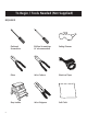
To Begin / Tools Needed (Not Supplied) REQUIRED 4 Flathead Screwdriver Phillips Screwdriver (4" recommended) Safety Glasses Pliers Wire Cutters Electrical Tape Step Ladder Wire Strippers Soft Cloth
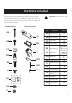
Hardware Included Carefully unpack and identify each part to make sure you have everything ready for installation. Lay out each part on a clean flat area such as a table or floor. Check to make sure you have the following: Hardware Bag Remote Control PART AA JJ BB KK CC LL DD MM EE FF GG ATTENTION: Parts are not to scale.
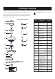
Package Contents Carefully unpack and identify each part to make sure you have everything ready for installation. Lay out each part on a clean flat area such as a table or floor. Check to make sure you have the following: A B Functional Fasteners O P C D Q E R F G H I J K L M N 6 ATTENTION: Parts are not to scale.
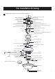
Fan Installation Drawing WARNING: Review important safety instructions before installation.
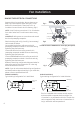
Fan Installation MAKING THE ELECTRICAL CONNECTIONS Prepare wiring from outlet box. Be sure there are no deep cuts in the exposed copper wiring as it could break off in the terminals. Cut and strip 1/2 in. of insulation from end of each wire if necessary. (Fig 1) Fig 1 outlet box NOTE: Do NOT strip any more than 1/2 in. of insulation from end of wires as this could cause a short at any time. black wire IMPORTANT: Wiring must not come down and around the face of powerplug receptacle.
Fan Installation WARNING: To avoid possible electric shock, be sure electricity is turned off at the main fuse box before wiring. WIRING DIAGRAM 3: Wiring Configuration with more than 1 of the same colored wires in the outlet box black (L1) (L2) W NOTE: Fan must be installed at a maximum distance of 6 m (20 ft.) from the transmitting unit for proper signal transmission between the transmitting unit and fan’s receiving unit.
Fan Installation INSTALLING THE POWERPLUG RECEPTACLE WITH RUBBER WASHER It is important for the powerplug receptacle to be flush with the ceiling surface. Outlet boxes are typically not even with the surface or sheet rock and the rubber washers will help to reduce or eliminate the gap. Follow these instructions. Fig 1. Fig 1. Outlet box is flush with the ceiling or the gap is less than 1.5mm, use 4mm rubber washer provided. Place the washer above the powerplug receptacle as shown. 0-1.
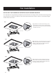
Fan Installation HANGING THE FAN 2. 1. rubber insert R B Q O Remove the rubber insert located on the canopy mounting screws (N) on both sides before installation. 3. Remove the cotter pin (R) and clevis pin (Q from the downrod of the canopy assembly (B). Note: For installation and use of longer downrod (option sold separately), instructions are available at www.gelightingandfans.com 4.
Fan Installation FINISHING THE FAN INSTALLATION 8. 7. O Tab Groove Rotate the canopy to the right (clockwise), continue turning the canopy until the screws (O) lock into place on the receptacle j slots. Note: You may need to loosen the canopy screws slightly, if you find it's difficult to lock the screws into the receptacle j slots. Make sure the tab on the mounting bracket socket is properly seated in the groove in the hanger ball/ downrod assembly. This will help to balance the ceiling fan.
Fan Installation Note: Before starting installation, disconnect the power by turning off the circuit breaker or removing the fuse at fuse box. Turning power off using the fan switch is not sufficient to prevent electric shock. 1. S Remove the three switch housing screws (S) preassembled on mounting plate of motor housing and save for later use. Note: To install the fan with light kit assembly, proceed to steps below.
Operation Instructions REMOTE CONTROL OPERATIONS Step 1. Restore power at circuit breaker and turn the wall switch to the on position (if using wall switch) to test for proper operation, Step 2. Open the battery compartment cover, and then install two 1.5-volt AAA batteries (KK) provided in the remote control bag. Ensure the batteries are installed correctly with regard to polarity (+ and -). “ O " and " I " dip switch "Sync" switch: + - AAA + Step 4.
Operation Instructions FAN REVERSE FUNCTION The reversible motor provides upward and downrod air flow for desired air circulation to save energy, see below for the details. Warm weather - Switch to the “Forward” position: A downward air flow creates a cooling effect as shown. This allows you to set your air conditioner on a higher setting without affecting your comfort. The reverse switch is located on the light kit assembly. Slide reverse switch to change fan rotation.
Remote Control Pairing Instructions REMOTECONTROLPAIRINGINSTRUCTIONS Important Note : By default, every fan has been pre-programmed at the factory and should be fully functional once installation is completed. There is no need to perform the pairing process. Should you find the fan or remote control not working or not fully functional after installation or during use, pairing of the remote control can be done by following the below simple procedures.
Blade Balancing The following procedure should correct most fan wobble. Check after each step. Check that all blade and blade bracket screws are secure. Most fan wobble problems are caused when blade levels are unequal. Check this level by selecting a point on the ceiling above the tip of one of the blades. Measure from a point on the center of each blade to the point on the ceiling. Measure this distance as shown in figure. Rotate the fan until the next blade is positioned for measurement.
Blade Balancing Kit The balancing kit should only be used if there is an unacceptable amount of fan wobble after completing all the steps in the user manual under “Attaching the Fan Blades”. 1. Turn the fan on and set the speed control setting to the speed at which the wobble is the greatest. fig. a 2. Turn off the fan and allow it to come to a complete stop. Mark the blades with masking tape number 1-5.
Safety Instructions PRODUCT MAINTENANCE Here are some suggestions to help you maintain your fan. Because of the fan’s natural movement, some connections may become loose. Check the support connections, brackets, and blade attachments twice a year. Make sure they are secure. (It is not necessary to remove fan from ceiling.) WARNING: Make sure the power is off at the electrical panel box before you attempt any repairs. Refer to the section “Making Electrical Connections”, page 8.
Manual del Usuario 1,32 m (52 pulgadas) Ventilador de techo Selena MODELOS: 20390 & 20406 120V 60Hz, HECHO EN CHINA Atención al cliente 1-866-885-4649 r re Service Team at 1-866-885-4649 re 9:00AM-5:00PM EST -Monday-Friday Nota: Videos de Instalación para ventiladores es con la tecnología de instalación Note: Installation videos fans with Powerplug quick connection technology rápida con enchufe GEfor pueden ser GE vistos y descargados en www.gelightingandfans.com can be viewed and downloaded on www.
Para su seguridad LEA Y GUARDE ESTAS INSTRUCCIONES 1. Para reducir el riesgo de descarga eléctrica, asegúrese de que la electricidad se haya apagado en el disyuntor o caja de fusibles antes de comenzar de instalación. 2. Todo el cableado debe cumplir con el Código Eléctrico Nacional “ANSI/NFPA 70” y los códigos eléctricos locales. Un electricista calificado y certificado debe realizar la instalación eléctrica. 3.
Guías Básicas Para Trabajar Con Electricidad 1. Antes de trabajar en un circuito, vaya al panel de servicio principal y retire el fusible o active el disyuntor que controla ese circuito. 2. Pegue una señal en el panel que advierta a otras personas que se alejen del ci rcuito mientras usted trabaja 3. Antes de tocar cualquier cable, use un voltímetro para asegurarse de que no esté bajo tensión. 4. Al comprobar el voltaje en un receptáculo, compruebe ambas salidas.
Herramientas Necesarias (No suministradas) NECESARIO 4 Destornillador de Cabeza Plana Destornillador de Estrella o Phillips (4” recomendado) Gafas de Seguridad Alicates Cortadores de Cable Cinta Eléctrica Escalera Pelacables Paño Suave
Herrajes Incluidos Desempaque con cuidado e identifique cada una de las piezas para que se asegure de que tiene todo listo para la instalación. Coloque todas las piezas en una superficie limpia y plana, como una mesa o alfombra. Revise para asegurarse de que tiene lo siguiente.
Contenido del Paquete Desempaque con cuidado e identi que cada una de las piezas para que se asegure de que tiene todo listo para la instalación. Coloque todas las piezas en una super cie limpia y plana, como una mesa o alfombra.Revise para asegurarse de que tiene lo siguiente. A B Sujetadores funcionales PARTE O P C D Q E R F G 6 ATENCIÓN: Las piezas no están a escala.
Dibujo de la instalación del ventilador ADVERTENCIA: Revise las instrucciones de seguridad importantes antes de la instalación Caja eléctrica (no suministrada) Cable blanco neutral Arandela plana Terminal de pasador de bloqueo Tornillo de madera Pasador de bloqueo Tornillo de montaje del dosel Soporte de montaje Cable blanco del receptor Receptor Cable Cable negro Cable a tierra Receptáculo del enchufe eléctrico Ranura de J Tornillo de la caja electrica Manija del soporte de montaje Cable a tierra del so
Instalación del ventilador CÓMO HACER LAS CONEXIONES ELÉCTRICAS cable negro Receptáculo del enchufe eléctrico L1 El cableado eléctrico (refiérase a la Fig 2 y Fig 3 si es Fig 2 necesario) se puede hacer como se muestra: Conecte el cable NEGRO del techo al terminal del enchufe eléctrico marcado L1. Asegure el cable apretando el pequeño tornillo en el costado. Conecte el cable BLANCO del techo al terminal del enchufe eléctrico que está marcado W.
Instalación del ventilador DIAGRAMA DE CABLEADO 3 Configuración de Cableado con más de 1 cable del mismo color en la caja eléctrica.
Instalación del ventilador INSTALANDO EL RECEPTÁCULO DEL ENCHUFE ELÉCTRICO CON LAS ARANDELAS DE GOMA Es importante que el receptáculo del enchufe eléctrico este empotrado a la superficie del techo. Las cajas eléctricas típicamente no están parejas con el techo y las arandelas de goma ayudarán a reducir o eliminar cualquier espacio. Siga estas instrucciones. Fig 1. 0-1.5mm Fig 1. La caja eléctrica está empotrada con el techo o el espacio es de menos de 1.5 mm, use una arandela de goma de 4mm provista.
Instalación del ventilador ENSAMBLAR EL VENTILADOR 2. 1. Pieza de goma R B Q O Retire la chaveta (R) y el pasador de horquilla (Q) del tubo del conjunto del dosel (B). Nota:Para la instalación y el uso de un tubo mas largo (opción y vendido por separado), hay instrucciones disponibles en www.gelightingandfans.com Retire las piezas de goma localizadas en los tornillos de montaje del dosel (O) en ambos lados antes de la instalación. 4. 3.
Instalación del ventilador TERMINANDO LA INSTALACION DEL VENTILADOR 8. 7. O Lengüeta Ranura Gire el dosel a la derecha (sentido horario), siga girando el dosel hasta que los tornillos (O) encajen en las ranuras-j del receptáculo. Nota: Gire el dosel a la derecha, siga girando el dosel hasta que los tornillos (O) encajen en las ranuras-j del receptáculo. 9. Asegúrese que la lengüeta en el receptáculo del soporte de montaje caiga apropiadamente en la ranura en el conjunto de bola / conjunto de varilla.
Instalación del ventilador Nota: Antes de comenzar la instalación, desconecte la energía apagando el disyuntor o retirando el fusible de la caja de fusibles. Apagar la energía utilizando el interruptor del ventilador no es suficiente para evitar una descarga eléctrica. 1. S Retire los tres tornillos de la cubierta del interruptor (S) preinstalado al plato de montaje de la cubierta del motor y guárdelos para ser usados mas tarde.
Instrucciones de Operación FUNCIONAMIENTO DEL CONTROL REMOTO Paso 1. Restablezca la electricidad en el panel de fusibles y encienda el interruptor de pared (si usa un interruptor de pared) para probar el funcionamiento adecuado. Paso 2. Abra la tapa del compartimento de las baterías, e instale dos baterías AAA de 1.5 volts (M) provistas en la bolsa del control remoto. Asegúrese que las baterías están instaladas correctamente basado en la polaridad (+ y -).
Instrucciones de Operación FUNCION DE REVERSA DEL VENTILADOR El motor reversible provee un flujo de aire descendente or ascendente para la circulacion de aire deseada para ahorrar energia, vea a continuacion para mas detalles. Clima cálido - Cambie a la pocision "Adelante". Un flujo de aire descendente crea un efecto refrescante tal como se muestra. Esto permite ajustar el aire acondicionado en una posicion mas alta sin afectar su comodidad.
Instrucciones Para la Sincronización del Control Remoto INSTRUCCIONES PARA LA SINCRONIZACIÓN DEL CONTROL REMOTO Nota Importante: De manera estandar cada ventilador ha sido configurado en la fábrica y debe funcionar sin problemas una vez este haya sido instalado completamente. No se require el processo de sincronización.
Balanceo de las aspas El siguiente procedimiento debe corregir la mayor parte del tambaleo del ventilador. Compruebe después de cada paso. Compruebe que todos los tornillos de las aspas y de los soportes de las aspas estén asegurados. La mayoría de los problemas del tambaleo se originan cuando los niveles de las aspas son desiguales. Compruebe este nivel seleccionando un punto en el techo por encima de la punta de una de las aspas. Mida desde un punto en el centro de cada aspa hasta el punto en el techo.
Juego Blade de Balance Balancing de Kit las Aspas Equipo de balanceo El kit de balanceo de las aspas solo se debe usar si hay tambaleos del ventilador luego de haber terminado todos los pasos de la instalación del ventilador en el manual bajo "Cómo colocar las aspas del ventilador". 1. Encienda el ventilador y coloque el mando de velocidad en la posición donde se produzca la mayor cantidad de tambaleo. fig. a Fije el clip plástico en el aspa 2. Apague el ventilador y deje que se detenga por complete.
Intrucciones de Mantenimiento de Usuario CUIDADO DE SU VENTILADOR Aquí hay algunas sugerencias para ayudarle a mantener su ventilador. Debido al movimiento natural del ventilador, algunas conexiones pueden aflojarse. Compruebe las conexiones de soporte, enchufes y adjuntos de las aspas dos veces al año. Asegúrese de que no están flojos. No es necesario quitar el ventilador. ADVERTENCIA: Asegúrese de que la energía está apagada en el panel principal antes de intentar cualquier reparación.