
Instructions / Assembly


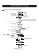


Fan Installation
8
Fig 2
Fig 1
powerplug
receptacle
-
ground
(green/
bare)
wire
white
wire
black wire
black wire
G
W
L1
Fig 3
L1
ground
black
L1
W
G
white wire
green/bare
wire
whi
outlet box
L2
red
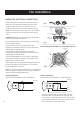
(CLOSE-UP VIEW of TERMINALS on Powerplug Receptacle)
white
green
black (live)
(L1)
(L2)
W
G-ground
WIRING DIAGRAM 2:
Typical Wiring Configuration for 2 Wall Switches
red (live 2)
WHITE
white
green
black(live 1)
(L1)
(L2)
W
G-ground
This Fan is supplied with a remote control receiver
and transmitter to operate the fan and light. The
L2 terminal is not activated on this fan. The red wire
can be capped off with a wire nut or inserted into L2.
Only 1 wall switch will be operational.
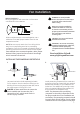
MAKING THE ELECTRICAL CONNECTIONS
t
e
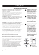
Prepare wiring from outlet box. Be sure there are no
deep cuts in the exposed copper wiring as it could
break off in the terminals. Cut and strip 1/2 in. of
insulation from end of each wire if necessary. (Fig 1)
NOTE: Do NOT strip any more than 1/2 in. of insulation
from end of wires as this could cause a short at any
time.
IMPORTANT: Wiring must not come down and around
the face of powerplug receptacle.
Connect GREEN/BARE wire from ceiling to terminal in
powerplug receptacle marked G. Secure the wire by
tightening the small set screw.
Reference the wiring configuration diagrams below for
other wiring options into the terminal. L1 is the only
active live terminal on this fan.
WIRING DIAGRAM 1:
Typical Wiring Configuration for 1 Wall Switch
NOTE: If you do not have standard wiring configurations
and have questions about the wiring in your outlet box,
please contact a qualified electrician.
Electrical wiring (refer to Fig 2 and Fig 3 as necessary)
Connect BLACK wire from ceiling to terminal in
powerplug receptacle marked L1. Secure the wire by
tightening the small set screw.
Connect WHITE wire from ceiling to terminal in
powerplug receptacle marked W. Secure the wire by
tightening the small set screw.
can be made as follows: