GE Security managed ethernet switches D-GES7600 Series Installation & Operation Instructions
Manageable 8/9-Port Switch PREFACE This manual describes how to install and use the D-GES7600 series EtherNav” Manageable 8/9-Port 10/100/1000 Base-TX (100/1000 Base-FX) Ethernet Switch. This switch integrates full wire speed switching technology with SNMP/RMON web-based management functions. The D-GES7600 series brings a simple answer to today’s complicated networking environments. To get the most out of this manual, you should have an understanding of Ethernet networking concepts.
Manageable 8/9-Port Switch INSTALLATION & OPERATION MANUAL / D-GES7600 PREFACE TABLE OF CONTENTS PRODUCT OVERVIEW Package Contents............................................................................................................................................ Product Features............................................................................................................................ Basic Features.....................................................................................
Manageable 8/9-Port Switch INSTALLATION & OPERATION MANUAL / D-GES7600 SWITCH MANAGEMENT CONTINUED…. SNMP-Based Network Management................................................................................... 22 Protocols............................................................................................................................................. 22 Management Architecture........................................................................................................
Manageable 8/9-Port Switch PRODUCT OVERVIEW Manageable 8/9-Port Switch 100FX Optical Ports 1000FX Port Console Port Power Ports Front View (D-GES7600-MM-S shown) 10/100TX Electrical Ports Fiber Loss Alarm PACKAGE CONTENTS When you unpack the product package, you shall find the items listed below.
Manageable 8/9-Port Switch PRODUCT FEATURES CONTINUED... Management Support: VLAN - 802.1Q tagged VLAN (up to 64 VLANs) - Quality of Service (QoS) Link Aggregation - Port-based Aggregation, up to four groups with a maximum of four ports each group - Load sharing based on source and destination MAC addresses Port-Mirroring - Port-mirroring provided through dedicated port, Port 1 Internet Working Protocols: Bridging - 802.1D Spanning Tree - 802.
Manageable 8/9-Port Switch FRONT PANEL DISPLAY (D-GES7600-MM-S Shown) 10/100TX Port Status Optical Status 1000FX Port Status Power Indicator 1. Power Indicator This LED comes on when the switch is properly connected to power. 2. Optical Status LED’s (FX) The ACT LED’s come on when data is present. (LED will flash at the rate data is transferred). The LNK LED’s will be on for 100FX speed transmission. 3. 10/100/1000TX Port Status LED’s The LED’s are located at each port, displaying status.
Manageable 8/9-Port Switch LED State Indication GREEN Steady A valid network connection established YELLOW Flashing Data transfer PHYSICAL PORTS This EtherNav” managed switch provides up to nine (10/100/1000TX and/or 100/1000FX combinations) ports: CONNECTIVITY - RJ-45 connectors - SC connector on fiber ports MODE SELECTION - 10BaseT full-duplex mode - 10BaseT half-duplex mode - 100BaseTX full-duplex mode - 100BaseTX half-duplex mode - 100BaseFX full-duplex mode - 100BaseFX half-duplex mode - 1000B
Manageable 8/9-Port Switch PLEASE NOTE: I. Half-duplex mode uses back pressure flow control to prevent the receiving buffer from being overrun by data from a source node. II. Full-duplex mode uses 802.3x flow control standard to prevent fast data traffic from overrunning slow data traffic. III. Auto-sensing mode is in use after auto-negotiating with the other end of the link.
Manageable 8/9-Port Switch PLEASE NOTE: I. Half-duplex mode uses back pressure flow control to prevent the receiving buffer from being overrun by data from a source node. II. Full-duplex mode uses 802.3x flow control standard to prevent fast data traffic from overrunning slow data traffic. III. Auto-sensing mode is in use after auto-negotiating with the other end of the link.
Manageable 8/9-Port Switch MULTICAST SWITCHING For multicast switching, the D-GES7600 checks whether the received frame is a BPDU. If a BPDU is received, the switch forwards the frame to the CPU for processing by the spanning tree protocol. Otherwise, the D-GES7600 performs the following processes: VLAN CLASSIFICATION Same as for unicast switching. LEARNING Same as for unicast switching.
Manageable 8/9-Port Switch VLAN A virtual LAN (VLAN) is a network of computers or peripherals that behave as if they are connected to the same wire, even though they may actually be physically located in different locations of a LAN. VLANs are similar to a group of end stations, perhaps on multiple physical LAN segments that are not inhibited by their physical location and can communicate as if they were on a common LAN.
Manageable 8/9-Port Switch BROADCAST CONTROL In traditional networks, traffic broadcasts to all network devices, whether they are the intended recipients or not. However, VLANs can be set up to contain only those devices that need to communicate with each other. As a result, VLANs considerably reduce network congestion. In addition, VLANs prevent broadcast storms from causing a network from crashing due to volumes of traffic.
Manageable 8/9-Port Switch REMOTE VLAN MEMBERSHIP Additionally to providing network management tools that allow network administrators to statically add and delete VLAN member ports, the switch also supports GVRP (GARP VLAN Registration Protocol). GVRP allows for dynamic registration of VLAN port members within switch and across multiple switches.
Manageable 8/9-Port Switch IGMP Snooping & IP Multicast Filtering Continued... If there is more than one router on the LAN performing IP multicasting, one of the routers is elected ‘querier’ and assumes the reponsibility. Based on the group membership information learned from the IGMP, a router can determine which (if any) multicast traffic needs to be forwarded to each of its ‘leaf’ sub-networks.
Manageable 8/9-Port Switch INSTALLATION This section gives step-by-step instructions about how to install the EtherNav” D-GES7600 switch: Selecting a Site for the Switch As with any electric device, you should place the switch where it will not be subjected to temperatures, humidity, or electromagnetic interference above the rated specifications. The site you select should meet the following requirements: - The ambient temperature should be between –40 to 74 degrees Celsius.
Manageable 8/9-Port Switch DIN Rail Back Mounting (-DB Option) The bracket provided will require the removal and re-installation of some cover screws as shown below. Bracket (-DB Option) Cover Screws DIN Rail Side Mounting (-DS Option) The bracket provided will require the removal and re-installation of one cover screw, the other screws are provided with the bracket as shown below.
Manageable 8/9-Port Switch Rack Mounting Single Unit (-RS Option) The brackets provided have screws included for proper mounting as shown below. Mounting Screws 4 Locations (Provided) Brackets (-RS Option) (Top View) (Front View) Note: All screws must be fastened and secured to insure adequate stability and strength.
Manageable 8/9-Port Switch Rack Mounting Dual Units (-RD Option) The brackets and braces provided have screws included for proper mounting as shown below.
Manageable 8/9-Port Switch CONNECTING TO POWER External Power Step One: Wire the supplied AC power adapter to the “A” receptacle plug at the front of the switch. — white stripe to pin 1 (+), black to pin 2 (-). Step Two: Attach the plug into a standard AC outlet with the appropriate AC voltage.
Manageable 8/9-Port Switch CONNECTING TO YOUR NETWORK Cable Type & Length Wire the supplied AC power adapter to the “A” receptacle plug at the front of the switch. — white stripe to pin 1 (+), black to pin 2 (-). Step Two: Attach the plug into a standard AC outlet with the appropriate AC voltage. It is necessary to follow the cable specifications below when connecting the switch to your network. Use appropriate cables that meet your speed and cabling requirements.
Manageable 8/9-Port Switch SWITCH MANAGEMENT This section explains the methods that you can use to configure management access to the switch. It describes the types of management applications and the communication and management protocols that deliver data between your management device (workstation or personal computer) and the system. It also contains information about port connection options.
Manageable 8/9-Port Switch Administration Console via RS-232 Console Port: Advantages: - No IP address or subnet needed - Text-based - HyperTerminal built into Windows 95/98/NT/2000 operating systems Disadvantages: - Must be near switch - Inconvenient for remote users Web-Based Browser Interface: Advantages: - Ideal for configuring the switch remotely - Compatible with all popular browsers - Can be accessed from any location - Most visually appealing Disadvantages: - Security can be compromised (hackers nee
Manageable 8/9-Port Switch ADMINISTRATION CONSOLE The administration console is an external, character-oriented, menu-driven user interface for performing system administration such as displaying statistics or changing option settings. Using this method, you can view the administration console from a terminal, personal computer, Apple Macintosh, or workstation connected to the switch’s console port. There are two ways to use this management method: direct access or mode Telnet access.
Manageable 8/9-Port Switch WEB MANAGEMENT The switch provides a browser interface that lets you configure and manage the switch remotely. After you set up your IP address for the switch, you can access the switch’s web interface applications directly in your web browser by entering the IP address of the switch. You can then use your web browser to list and manage switch configuration parameters from one central location, just as if you were directly connected to the switch’s console port.
Manageable 8/9-Port Switch SNMP-BASED NETWORK MANAGEMENT If you enable the SNMP function through the console port, you can use an external SNMPbased application to configure and manage the switch. This management method requires the SNMP agent on the switch and the SNMP Network Management Station to use the same community string. This management method, in fact, uses two community strings: the ‘get’ community string and the ‘set’ community string.
Manageable 8/9-Port Switch MENU-DRIVEN CONSOLE MANAGEMENT The switch provides a menu-driven console interface for configuration purposes. The switch can be configured either locally through its RS-232 port or remotely via a Telnet session. This section describes how to configure the switch using its menu-driven console. Logging On To The Switch At the screen prompt: Switch Console Login: Password: Login Name Enter the console interface factory default console name admin.
Manageable 8/9-Port Switch SWITCH MANAGEMENT SCREEN Basic Management Refer to performing basic management activities. Advanced Management Refer to performing advanced management activities. Logout Highlight this option and press to log out. Save Settings Highlight this option and press to save the current settings and remain in the configuration program. Restore Default Settings Highlight this option and press to restore the factory default settings.
Manageable 8/9-Port Switch Navigating Through the Console Interface The console interface consists of a series of menu boxes. Each menu box has several options, which are listed vertically. Move the highlight to select an option as you wish, press the key to activate that option. Press this key….
Manageable 8/9-Port Switch Step 2: Highlight a desired option and press . Or press to EXIT. NOTE: The changes will be effective after you press the , but will not be saved until you select the Save Setting function. GENERAL MANAGEMENT CONFIGURATIONS Step 1: Highlight General from [Basic Management] screen and press .
Manageable 8/9-Port Switch Step 2: System Name System Name is highlighted. Press if you want to change it. Step 3: Location Move to highlight Location and press if you want to change it. Step 4: admin Password Move to highlight Admin Password and press If you want to change it. Step 5: guest Password Move to highlight guest Password and press if you want to change it.
Manageable 8/9-Port Switch LAN Port Configurations Step 1: Highlight LAN Port from [Basic Management] screen, and press . Step 2: Speed & Flow Control Speed & Flow Control is highlighted. Press if you want to set speed or flow control on port. Step 3: Highlight All Ports and press to configure at one time. Or move to highlight each port and press to configure individually.
Manageable 8/9-Port Switch Step 4: Port Setting Options screen appears. Highlight Speed & Flow Control, and press . Step 5: Line Speed For Line Speed, move to highlight a desired setting from Speed Options, and press . Note: In the Speed Options, HD denotes half-duplex and FD denotes full-duplex. Step 6: Press to previous screen. Highlight Flow Control, and press .
Manageable 8/9-Port Switch Step 8: Press to a previous screen as shown in Step 3. Step 9: Admin. Control Highlight All Ports and press to configure at one time. Or move to highlight each port and press to configure individually. Step 10: For Admin Control, move to highlight Up or Down from Admin Status Options. Step 11: The port is set as Admin Down to stop TX/RX transmission. To allow transmission on the port, move to highlight Up from the options in Step 10.
Manageable 8/9-Port Switch Console Port Configurations Step 1: Move to highlight Console Port from [Basic Management] screen. Step 2: Baud Rate Baud Rate is highlighted. Press if you want to change the current console baud rate. Step 3: Flow Control Press to return to [Basic Management] screen when completed. Step 4: Modem Control Step 5: Modem Setup String Not Supported. Step 6: Return to Basic Management Press to return to [Basic Management] screen when completed.
Manageable 8/9-Port Switch Alarm Configurations Step 1: Move to highlight Alarm from [Basic Management] screen. Step 2: Set optical ports Loss of Signal. Step 3: Highlight desired function.
Manageable 8/9-Port Switch PERFORMING ADVANCED MANAGEMENT ACTIVITIES Advanced management activities consist of L2 Switching Database/ IP Networking/ Bridging/ Static Filtering/ Spanning Tree/ SNMP/ Other Protocols/ Port Trunking/ Port Mirroring/ File Transfer. To Perform Advanced Management Activities Step 1: Highlight [Advanced Management] from Switch Management screen, and press . The [Advanced Management] screen appears: Step 2: Move to highlight a desired option and press .
Manageable 8/9-Port Switch L2 Switching DataBase Step 1: VLAN Perspective Highlight L2 Switching Database from [Advanced Management] screen, and press . Step 2: The VLAN Perspective is highlighted. Press to view VLAN info of the default VLAN or if you want to obtain a VLAN perspective instead of the default VLAN. Note: Default VLAN: The IEEE802.1Q standard defines VLAN ID #1 as the default VLAN. The default VLAN includes all the ports as the factory default.
Manageable 8/9-Port Switch Step 4: Press and the following screen appears. Press <+> to add new switch ports to the newly created VLAN. Step 5: Move to highlight a suitable option from Port Options and press , e.g. Untagged Ports. Step 6: From Select Untagged Ports, press to select All Ports or move to highlight each port individually and press . Similar procedure when you select Tagged Ports and Forbidden Ports in Step 5.
Manageable 8/9-Port Switch Step 7: Press to a previous screen as shown in Step 2. Step 8: Delete VLAN Highlight a VLAN ID and press <-> to delete it. Note: The default VLAN cannot be deleted. IP Multicast Group Perspective Step 1: Move to highlight IP Multicast Group Perspective from L2 Switching Database screen, and press . Step 2: Move to highlight an address to view information associated with this IP multicast group.
Manageable 8/9-Port Switch MAC Address Perspective Step 1: Move to highlight MAC Address Perspective from L2 Switching Database screen, and press . Step 2: Enter a MAC address to view characteristics information, corresponding VLAN’s, and corresponding ports in the switching database. Port Perspective Step 1: Move to highlight Port Perspective from L2 Switching Database screen, and press . You can view VLAN activities and RMON statistics here.
Manageable 8/9-Port Switch Step 2: Per Port VLAN Activities Per Port VLAN Activities is highlighted. Press . Step 3: Move to highlight a port and press . Example: select Port 1 to view corresponding VLAN Activities. Step 4: View or search by MAC address individually. Step 5: Press to return to a previous screen as shown in Step 1.
Manageable 8/9-Port Switch Step 6: Per Port Statistics Move to highlight Per Port Statistics and press . Step 7: Move to highlight a port and press . Example: select Port 1 to view corresponding VLAN Activities. Press [R] to reset counter for this port.
Manageable 8/9-Port Switch Step 8: Per Port MAC Unit Move to highlight Per Port Priority and press . Step 9: Move to highlight a port and press . Example: select Port 1 to view corresponding priority level.
Manageable 8/9-Port Switch IP Networking Step 1: Move to highlight IP Networking from [Advanced Management] screen, and press . Step 2: IP & RIP Settings Highlight IP & RIP Settings from IP Networking, and press . Step 3: The screen shows a list of VLAN IDs, IP addresses, subnet masks, proxy ARPs, and RIPs currently defined.
Manageable 8/9-Port Switch Step 4: Move to highlight the row that contains the parameters you want to change, and press . ARP Table Step 1: Highlight ARP Table from IP Networking, and press . Routing Table Step 1: Highlight Routing Table from IP Networking, and press .
Manageable 8/9-Port Switch DHCP Gateway Step 1: Highlight DHCP Gateway from IP Networking, and press . Step 2: Select VLAN, and press . Step 3: Highlight DHCP Gateway for Enabling or Disabling function. Ping Settings Step 1: Move to highlight Ping from IP Networking, and press .
Manageable 8/9-Port Switch Step 2: Host Move to highlight Host, and press . Step 3: Enter 4 decimal bytes (dot separated) as the IP address to ping. Step 4: Count Move to highlight Count, and press . Step 5: Specify a packet count number from 1 to 999, or type 0 for an infinite packet count, and press . Step 6: Size (bytes) Move to highlight Size, and press . Step 7: Specify a packet size from 0-1500, and press .
Manageable 8/9-Port Switch Bridging Step 1: Move to highlight Bridging from [Advanced Management] screen, and press . Step 2: Aging Time Move to highlight Aging Time, and press . Enter a decimal number as bridge aging period in seconds or, enter 0 for no aging. Step 3: Flood Limits for all Ports Move to highlight Flood Limit for All Ports, and press . Enter a decimal number as flood limit in packets per second or, enter 0 for no limit.
Manageable 8/9-Port Switch Step 2: Source/Destination MAC Address Out-Filters Move to highlight Source MAC Addresses or Destination MAC Addresses for static filtering, and press . Source Filter Destination Filter MAC Address in Filters Step 3: Move to highlight MAC Address Filters from Static Filtering, and press .
Manageable 8/9-Port Switch MAC Address in Filters Step 4: Add/Delete/Search Press [+] on keypad to add a specific MAC address to be filtered. Press [-] to delete a specific MAC address from being filtered. Press [S] to search through current list of MAC addresses in the static filtering database. The static filtering database maximum capacity is 64. Caution: User’s Manual * No prec autionary messa ge appears before you delet e a speci fic MAC address from being fi ltered.
Manageable 8/9-Port Switch Rapid Spanning Tree Functions Step 1: Move to highlight Rapid Spanning Tree from [Advanced Management] screen, and press . Step 2: Spanning Tree Configurations Move to highlight Spanning Tree Configurations if you want to change Spanning Tree Protocol Configurations. Step 3: Spanning Tree Protocol Press to enter Spanning Tree Options. Decide to have it Disabled or Enabled. Step 4: Bridge Priority Move to highlight Bridge Priority, and press .
Manageable 8/9-Port Switch Step 6: Max Age (sec) Move to highlight Max Age, and press . Type a decimal number for the max age. Step 7: Forward Delay (sec) Move to highlight Forward Delay, and press . Type a decimal number for the forward delay. Spanning Tree Port States Step 1: Move to highlight Spanning Tree Port States if you want to change per port administration status, and press . Step 2: Move to highlight a port if you want to change its administration status, and press .
Manageable 8/9-Port Switch Spanning Tree Port Priorities Step 1: Move to highlight Spanning Tree Port Priorities if you want to change the priority level per port, and press . Step 2: Move to highlight All Ports or each port individually, and press . For new priority value, type a decimal number from 0-255, and press . A low value gives the port a greater likelihood of becoming a Root port.
Manageable 8/9-Port Switch Edge Port Point-to-Point Link SNMP Functions Step 1: Move to highlight SNMP from [Advanced Management] screen, and press . Step 2: SNMP Options Move to highlight SNMP, and press . Decide to have it Disabled or Enabled.
Manageable 8/9-Port Switch Step 3: Get Community Name Move to highlight Get Community Name, and press . Enter text and press . Step 4: Set Community Name Move to highlight Set Community Name, and press . Enter text and press . Step 5: Trap Community Name Move to highlight Trap Community Name 1 and press . Enter text and press . Repeat to specify up to three more trap community names.
Manageable 8/9-Port Switch Other Protocols Step 1: Move to highlight Other Protocols from [Advanced Management] screen, and press . Step 2: GVRP Move to highlight GVRP, and press . Decide to have it Disabled or Enabled. Step 3: IGMP Move to highlight IGMP, and press . Decide to have it Disabled or set in either Passive or Active mode. Link Aggregation Step 1: Move to highlight Link Aggregation from [Advanced Management] screen, and press .
Manageable 8/9-Port Switch Aggregation Port Status Step 2: Move to highlight Aggregation Port Status, and press . Step 3: Select Actor or Partner for the Port selected.
Manageable 8/9-Port Switch Actor Screen Partner Screen Aggregation Port Settings Step 4: Move to highlight Aggregation Port Settings, and press .
Manageable 8/9-Port Switch Aggregation Port Settings Step 5: Select desired Port. Aggregation Port Statistics Step 6: Move to highlight Aggregation Port Statistics, and press . Step 7: Select desired Port.
Manageable 8/9-Port Switch Fast Link Aggregation Step 8: Move to highlight Fast Link Aggregation, and press . IEEE802.3 Aggregation Step 9: Move to highlight IEEE802.3 Aggregation, and press . Step 10: Select desired Aggregator.
Manageable 8/9-Port Switch Port Mirroring Step 1: Move to highlight Port Mirroring from [Advanced Management] screen, and press . You can mirror one port to Port 1. Step 2: Press to enter Port Mirroring Options. Step 3: Mirror From Press to enter Mirror From Options, listing the ports that can be mirrored from.
Manageable 8/9-Port Switch Step 4: Move to highlight the port you want to mirror from and press . Step 5: Mirror Mode Move to select Mirror Mode. From Mode Options, decide whether the port to be mirrored from will be receiving or transmitting. Step 6: Press when completed. Quality of Service (QoS) Step 1: Move to highlight QoS Setup from [Advanced Management] screen, and press . Global Setting Step 2: Move to highlight Global Setting, and press .
Manageable 8/9-Port Switch Logical Port Step 3: Move to highlight Logical Port, and press . Step 4: Move to highlight User Defined Port. Step 5: Select Port to be Defined. Step 6: Move to highlight Well-Known Port.
Manageable 8/9-Port Switch Step 7: Select Port to be Defined. Step 8: Move to highlight Range Port. VLAN Step 1: Move to highlight VLAN from QoS Setup, and press . Step 2: Assign desired port to a VLAN. ToS Step 1: Move to highlight ToS from QoS Setup, and press . Step 2: Highlight desired port to be set.
Manageable 8/9-Port Switch Tx Queue Setting Step 1: Move to highlight Tx Queue Setting from QoS Setup, and press . Step 2: Set Queue for optional Port 9. Fixed Priority Step 1: Move to highlight Fixed Priority from QoS Setup, and press . Step 2: Select desired Port. Rate Control Step 1: Move to highlight Rate Control from QoS Setup, and press .
Manageable 8/9-Port Switch SENDING AND RECEIVING FILES The TFTP protocol is used to download upgraded software to the switch. A VLAN with the proper IP address and routing path to the TFTP server must be configured for the switch to access the specified TFTP server. Step 1: Move to highlight File Transfer from [Advanced Management] screen, and press . Step 2: Receive File Via TFTP Move to highlight Receive File Via TFTP and press .
Manageable 8/9-Port Switch Step 5: Press when completed. Step 6: A dialog box appears to ask if you want to transfer file now. Highlight [Yes] and press to start file transfer, or move to highlight [No] and press to deny it. Press to exit. Step 7: Send File Via TFTP Move to highlight Send File Via TFTP, and press . Step 8: If the default File Type is not the one you intend to send, press . Select the file type you intend to send and press .
Manageable 8/9-Port Switch Logout To log out, highlight Logout from [Switch Management] screen, and press . Please remember to save settings you have changed before you log out. Save Settings To save the current settings and remain in the configuration program, highlight Save Settings from [Switch Management], and press . Restore Default Settings To restore the factory default settings, highlight Restore Default Settings from [Switch Management], and press .
Manageable 8/9-Port Switch WEB-BASED BROWSER MANAGEMENT The EtherNav” D7600 switch provides a web-based browser interface for configuring and managing the switch. This interface allows you to access the switch using a preferred web browser. This section describes how to configure the switch using its web-based browser interface. LOGGING ON TO THE SWITCH Switch IP Address In your web browser, specify the IP address of the switch. Login ID Enter the factory default login ID: admin.
Manageable 8/9-Port Switch UNDERSTANDING THE BROWSER INTERFACE The web browser interface provides three point-and-click buttons at the upper field of the screen for configuring and managing the D-GES7600. The Basic Setup/General parameters appear at the lower field of the screen. These parameters can also be displayed by clicking Basic Setup button and select General in sub-menu.
Manageable 8/9-Port Switch PERFORMING FILE ACTIVITIES To Perform File Activities: Click the [File] button at the upper field of the main display, the menu options appear. Step 1: Saving Setting Click Saving Setting to save your configuration settings. Step 2: When you click it, a message asks "Are you sure you want to save setting? ", click OK to save it or Cancel to abort it. Step 1: Receive File Via TFTP Click Receive File Via TFTP on the [File] display.
Manageable 8/9-Port Switch Step 1: Reboot Click Reboot on the [File] display. Step 2: When you click it, a message asks "Are you sure you want to save setting?", click OK to save it or Cancel to abort it. Step 1: Logout Click Logout on the [File] display. Step 2: When you click it, a message asks "Are you sure you want to save setting?", click OK to save it or Cancel to abort it.
Manageable 8/9-Port Switch Step 2: System Name Click in System Name text box on the field of Basic Setup/General. Step 3: Type a system name if it is blank, or replace the current system name with a new one. Step 4: Location Click in Location text box on the field of Basic Setup/General. Step 5: Type a location name if it is blank, or replace the current location name with a new one.
Manageable 8/9-Port Switch Step 2: Port Status Click Port Status to view the line speed and flow control for all ports. Note: The information displayed automatically updates every 15 seconds, without requiring you to refresh the window. Step 3: Port Setting Click Port Setting to access the configuration information for all ports. Step 4: In the Port column, click the port you want to configure. E.g. click Port 1.
Manageable 8/9-Port Switch Step 5: Click the drop-down menu under Admin Setting, decide to disable or enable it. Note: Disable - places the port in DOWN state. In this state, packets cannot be switches to and from the port. Enable: places the port in UP state. In this state, packets can be switched to and from the port. Step 6: Click the drop-down menu under Speed/Duplex Options if you want to change the line speed and duplex settings.
Manageable 8/9-Port Switch Console Port Configuration Step 1: To access the console port configuration parameters, click Basic Setup button first and then click Console Port. Step 2: Baud Rate Click an appropriate speed from Baud Rate drop-down menu on the field of Basic Setup/Console Port Configuration. Note: Auto: allows the switch to Auto-baud between 9600bps and 115,200bps All the other selections force a specific console baud rate.
Manageable 8/9-Port Switch PERFORMING ADVANCED SETUP ACTIVITIES To Perform Advanced Setup Activities: Click the [Advanced Setup] button at the upper field of the main display, the menu options appear. MAC Address Management Step 1: From the Advanced Setup menu, point to MAC Address Management to view VLANs and their associated MAC addresses. Step 2: Per VLAN View Click Per VLAN View first and click on the port that you want to view. Close the VLAN Activities window when finished viewing.
Manageable 8/9-Port Switch Step 3: Per Port View Click Per Port View first and click on the port that you want to view. Close the Per Port VLAN Activities window when finished viewing. Step 4: Individual MAC View From the Advanced Setup menu as shown in Step 1, point to MAC Address Management. Click Individual MAC View. Step 5: Click in the Enter MAC Address text box and type the MAC address that you want to view. Then click on the Get Information button.
Manageable 8/9-Port Switch Step 1: IP & RIP Settings Click IP & RIP Settings to access IP and RIP settings. A list of VLAN Ids appears, along with their corresponding IP address and subnet mask. Step 2: In the VLAN ID column, click a VLAN ID whose settings you want to view and/or change. Step 3: To change the IP Address, click in the text box and type a new address. Alternatively, you can use the Delete IP button to delete the IP address.
Manageable 8/9-Port Switch Step 14: Specify whether split horizon is to be used. Step 15: Specify whether poisoned reverse is to be used. Step 16: Specify whether the switch is to send triggered responses. Step 17: When you finished with these selections, click Update Setting. A confirmation window appears. Click to close the confirmation window. Per Port Statistics Step 1: To access per port statistics, click the Advanced Setup button, and then click Per Port Statistics from the selection menu.
Manageable 8/9-Port Switch Step 2: Aging Options Click the drop-down list for Disabled (No Aging) or Set Aging Time. Step 3: Aging Time Click the text box and type a decimal number as bridge aging period in seconds. Step 4: Flood Limit Click the drop-down list for No Flooding, Controlled Flooding, Unlimited Flooding. Step 5: Flood Limit for All Ports Click the text box and type a decimal number as flood limit in packets per second.
Manageable 8/9-Port Switch Step 3: The Static Source MAC Filter window appears. Click in the Source MAC Address Filter text box and type a unique MAC source address you want to add. Then click the Add button. Step 4: A confirmation window appears. Close the confirmation window. Step 5: If you no longer need a source MAC address, click Delete MAC Addr button to delete it in Step 2. Step 6: The Delete Source MAC Address window appears.
Manageable 8/9-Port Switch IP Multicast Group To view the IP multicast group addresses, click the Advanced Setup button, and click IP Multicast Group in the selection menu. The information is read-only. VLAN Perspective To view the VLAN configuration information, click the Advanced Setup button, and point to VLAN Perspective in the selection menu. Step 1: VLAN Configuration Click VLAN Configuration. Step 2: Click on a VLAN ID whose VLAN configuration you want to change.
Manageable 8/9-Port Switch IP Multicast Group To view the IP multicast group addresses, click the Advanced Setup button, and click IP Multicast Group in the selection menu. The information is read-only. VLAN Perspective To view the VLAN configuration information, click the Advanced Setup button, and point to VLAN Perspective in the selection menu. Step 6: The Add a VLAN Entry window appears. Step 7: Click in the VLAN ID text box and specify a new VLAN ID number.
Manageable 8/9-Port Switch Link Aggregation To view the spanning tree perspective parameters, click the Advanced Setup button, and point to Link Aggregation in the selection menu. Step 1: Aggregation Port Status To view and/or change the Aggregation configurations, click Port Link Aggregation from the above screen. Step 2: For Link Aggregation, specify whether you want to have it Disabled or Enabled by clicking the drop-down list.
Manageable 8/9-Port Switch Step 7: Click Update Setting. A confirmation window appears. Close the confirmation window. Step 1: Port Setting To view and/or change the Spanning Tree configurations by port, click the Advanced Setup button, point to Link Aggregation in the selection menu, and click Aggregation Port Settings. Step 2: In the Port column, click the port whose Aggregation information you want to view. Step 3: For Port Priority, click in the text box and type a decimal number between 0 and 255.
Manageable 8/9-Port Switch SNMP To view and/or change all SNMP-related information, click the Advanced Setup button, and click SNMP in the selection menu. The SNMP Configurations window appears. As shown below, the factory-default SNMP value is enabled and the factory-default Community Name value is public. Step 1: SNMP For SNMP, specify whether it is Disabled or Enabled by clicking the drop-down list. Step 2: Get Community Name For Get Community Name, click in the text box and type a get community name.
Manageable 8/9-Port Switch Step 9: Link Up Trap For Link Up Trap, specify whether it is Disabled or Enabled by clicking the drop-down list. Step 10: Authentication Failure Trap For Authentication Failure Trap, specify whether it is Disabled or Enabled by clicking the drop-down list. Step 11: Rising Alarm Trap For Rising Alarm Trap, specify whether it is Disabled or Enabled by clicking the drop-down list.
Manageable 8/9-Port Switch Port Mirroring To use the switch’s mirroring capability to mirror one port to Port 1, click the Advanced Setup button, and click Port Mirroring in the selection menu. Click Port 1 in the Mirror To column. Step 1: Mirror From In the Mirror From column, select a "mirror from" port by clicking the drop-down list. Data traffic from this port will mirror to Port 1.
Manageable 8/9-Port Switch SNMP & RMON MANAGEMENT This section describes the switch’s Simple Network Management Protocol (SNMP) and Remote Monitoring (RMON) capabilities. OVERVIEW RMON is an abbreviation for the Remote Monitoring MIB (Management Information Base). RMON is a system defined by the Internet Engineering Task Force (IETF) document RFC 1757, which defines how networks can be monitored remotely.
Manageable 8/9-Port Switch Warm start Cold start Link up Link down Authentication failure Rising alarm Falling alarm Topology alarm MIB-2 defines a set of manageable objects in various layers of the TCP/IP protocol suites. MIB-2 covers all manageable objects from layer 1 to layer 4 and, as a result, is the major SNMP MIB supported by all vendors in the networking industry. The switch supports a complete implementation of SNMP Agent and MIB-2.
Manageable 8/9-Port Switch Bridge Groups Supported The switch supports the following four groups of Bridge MIB (RFC 1493): - The dot1dBase Group – a mandatory group that contains the objects applicable to all types of bridges. - The dot1dStp Group – contains objects that denote the bridge’s state with respect to the Spanning Tree Protocol. If a node does not implement the Spanning Tree Protocol, this group will not be implemented.
Manageable 8/9-Port Switch SPECIFICATIONS Manageable 8/9-Port Switch 10/100/1000BaseT/TX auto-negotiating ports with RJ-45 connectors and 100/1000BaseFX fiber ports combination Applicable Standards IEEE 802.3 10BaseT IEEE 802.
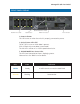
Manageable 8/9-Port Switch APPENDIX A - CONNECTOR PINOUTS Pin arrangement of RJ-45 connectors: 8 1 The following table lists the pin out of 10/100/1000BaseT/TX ports.
Limited Warranty a. GE Security warrants that its products are free from defects in workmanship and materials, and will conform to GE Security’s published specifications, subject to the terms of this limited warranty. With respect to any product furnished by GE Security, the foregoing shall apply only to failures to meet said warranty that appear within the applicable warranty period set forth in the Security Equipment Return and Warranty Policy Statement on our website.