Installation Instructions Built-in Dishwasher If you have questions, call 800.GE.CARES(800.432.27371or visit our Website at: GEAppliances.com. In Canada, please call 1.800.561.3344 or visit www.geappliances.ca BEFORE YOU BEGIN Read these instructions carefully. IM PO RTA N T - completely IM PORTANT - The dishwasherMUST be installed to allow for future removal from the enclosure if service is and required. Observeallgoverningcodesand ordinances. .
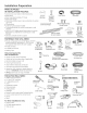
Installation Preparation PARTS SUPPLIED IN INSTALLATION ? PACKAGE: . Junction box cover and #!0 hex-head screw . Hose clamp . Drain hose (approximately 78" long) . Drain hose hanger .2 #8-!8 hex head screws to secure brackets to washer tub frame Junction #10 Hex-Head Box Cover Junction .2 Plug buttons .2 side trim pieces (some models) .2 mounting brackets for wood countertops or side cabinets Hose Clamp Box Screw ?? 112" long n #8 Hex-Head Mounting Bracket Screws Drain Hose Hanger .
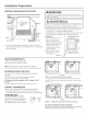
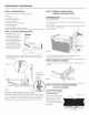
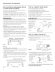
Installation Preparation PREPARE DISHWASHER ENCLOSURE kWARNING: To reducethe risk of electric shock,fire, or injury to persons,the installer must ensurethat the dishwasheris completelyenclosedat the time of installation.
Installation Preparation PREPARE ELECTRICAL WIRING / WARNING: _//_/_ I _'__ Receptacle Alternate Location \ \ FORPERSONAL SAFETY: Removehousefuse or open circuit breaker beforebeginning installation.Do not usean extensioncord or adapter plug with this appliance. ADVERTENCIA: Cabinet PARASEGURIDAD PERSONAL: Quite el fusible o abra el interruptor de circuitos antes de comenzarla instalaci6n.No utilice un cable de extensi6no un enchufe adaptador con este artefacto. Electrical Requirements .
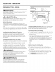
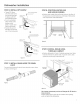
Installation Preparation PREPARE HOT WATER LINE NOTE:GE recommends copper tubing for the water line, but if you choose to use flexible hose, use GE'sW×28×326, flexible braided hose. . The water supply line (3/8" copper tubing or flexible braided hose) may enter from either side, rear or floor within the shaded area shown in Figure F. . The water supply line may pass through the same hole as the electrical cable and drain hose. Or,cut an additional 1-1/2" diameter hole to accommodate the water line.
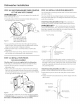
Dishwasher Installation STEP 1:PREPARATION STEP 3: REMOVE WOOD BASE, INSTALL LEVELING LEGS Locate the items in the installation package: , Screws Junction box cover , Drain hose and clamp , Mounting brackets , Trim pieces (on some models) , Drain hose hanger , Owner's Manual , Product samples and/or coupons IMPORTANT Damage - Do not kickoffwood bose! willoccur. , Move the dishwasher close to the installation location and lay it on its back.
Dishwasher Installation STEP 6: INSTALL 90 ° ELBOW , Thread 90 ° elbow onto the water valve. Use thread seal tape for elbows with 3/8" NPTexternal threads. , Do not overtighten elbow. Water valve bracket could bend or water valve fitting could break. , Position the end of the elbow to face the rear of the dishwasher. Front of Dishwasher , Position water supply line and house wiring on the floor of the opening to avoid interference with base of dishwasher and components under dishwasher.
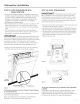
Dishwasher Installation STEP 10: SLIDE DISHWASHER THREE-FOURTHS OF THE WAY INTO CABINET IM PORTANT - oonotpush against frontpanel with knees. Damage will occur. , Grasp the sides of the front panel and slide dishwasher into the opening a few inches at a time. STEP 12: INSTALL MOUNTING BRACKETS You will need the mounting brackets and 2 #8 hex-head screws set aside in Step 1.
Dishwasher Installation STEP 13: PUSH DISHWASHER INTO FINAL POSITION , Check the tub insulation blanket, if equipped, to be sure it is smoothly wrapped around the tub. It should not be "bunched up" and it must not interfere with the door springs. If the insulation is "bunched up" or interfering with the springs, straighten and recenter the blanket prior to sliding the dishwasher into its final position. . Slide the dishwasher into the final position by pushing on the sides of the door panel.
Dishwasher Installation STEP 15: POSITION DISHWASHER, TO COUNTERTOP OR CABINET SECURE In this step you will need the 2 Phillips special head screws from the screws set aside in Step 1. The dishwasher must be secured to the countertop or the cabinet sides. When the underside of the countertop is wood, use Method 1. Use Method 2 when the underside of the countertop is made of a material, such as granite, that will not accept wood screws. IMPORTANT - Preventdoorpaneland control panel damage.
Dishwasher Installation STEP 17: CONNECT DRAIN LINE (Cont.) . Connect drain line to air gap, waste tee or disposer using the previously determined method. Secure hose with a screw-type clamp. Method 1 - Air gap with waste tee or disposer STEP 18: CONNECT POWER SUPPLY Ifa power cord with plug is already installed proceed to Step 19. AWARNING: If house wiring is not 2-wire with ground, a ground must be provided by the installer.
Dishwasher Installation STEP 19: PRETEST CHECKLIST STEP 20: DISHWASHER WET TEST Reviewthislist afterinstalling yourdishwasherto avoid chargesfora servicecall thatisnotcoveredby your wa r ra nty. ,Check to be sure power is OFF. ,Turn on power supply or plug power cord into outlet, if equipped. ,Open door and remove all foam and paper packaging. ,Locate the Owner's Manual set aside in Step 1. ,Read the Owner's Manual for operating instructions. , Select a cycle to run and push the Start/Reset pad.
Dishwasher Installation STEP 21: POSITION SOUND BARRIER AND INSULATION {on some models) STEP 22: REPLACE TOEKICK . Place toekick against the legs of the dishwasher. Skip this step if the sound barrier is not assembled to the dishwasher. . Locate the sound insulation package inside the dishwasher. , Locate the control box. Control Box Screws Figure CC , Peel off the paper from the insulation. , Apply the insulation to the underside of the control box and flush with its front face as shown.
Notes 14
Notes 15
SPECIFICATIONS SUBJECT TO CHANGE WITHOUT NOTICE GEAppliances General Electric Company Louisville, Kentucky/40225 GEAppliances.
Appareils m@nagers Directives d'instailation Lave-vaisselle encastr@ Pour toute question, composez le 1.800.561.3344 ou visitez notre site Web: www.electromenagersge.ca AVANT DE COMMENCER IM PORTANT Veuillez lira attentivement toutes les directives mani_re 6 ce qu'il puisse _tre sorti de son emplacement si des r@arations sont n6cessaires. qui suivent. IM PO RTANT - Observez touslescodes et ordonnances en vigueur. .
Pr6paration pour I'installation ? PIt CES FOURNIES DANS UEMBALLAGE: , Couverclede la botte dejonction etvis 6 t6te hexagonalen° 10 , Collier \ Couvercle , Boyaude vidange (198cm/78 po de long) , Supportde twau de vidange) , 2 vis (3t6te hexagonale no 8-18 pour fixer lessupports au cadre de la cuve du lave-vaisselle , 2 Boutonsde bouchon , 2 Moulureslat6rales(certainsmod61es) , 2 supports de montage pour comptoirs ou armoires lat6ralesen bois , 2 vis (3t6te sp6ciale Phillipsn° 8-18 x !5,8 mm (5/8po) pou
Preparation pour I'installation PRI_PARATION DE L'OUVERTURE DANS LES ARMOIRES Le lave-vaisselle doit _tre install6 de faqon 6 ce que le boyau de vidange mesure au maximum 3.66 m_tres (12 pieds) pour assurer une vidange ad6quate. Le dessus, les c6t6s et I'arri_re du lave-vaisselle doivent _tre compl_tement dissimul6s 6 I'int@ieur de I'ouverture. Le lave-vaisselle ne doit soutenir aucune pattie de la structure des armoires.
Preparation pour I'installation PRE PARATION DU C#,BLAGE E LECTRIOUE _'/ / AVERTISSEMENT: _ POURVOTRESECURITE PERSONNELLE: Enlevezle fusible ou d@clenchezle disjoncteurau panneau de distribution principal avant de commencer I'installation.N'utilisezpas une rallonge @lectriqueou un adaptateur de fiche avec cet appareil. 46 cm (18 po) -- 46 cm i÷ (18 po) I /1÷'- Alimentotion @lectrique .
Preparation pour I'installation PRI PARATION DE L'ALIMENTATION EAU CHAUDE EN REMARQUE:GE recommande I'utilisation d'un tuyau en cuivre pour la conduite d'alimentation en eau, mais vous pouvez choisir un boyau flexible tress# no W×28×326 de GE. , La conduite d'alimentation en eau (tuyau de cuivre de 9,5 mm [3/8 po] ou boyau flexible tress#) peut entrer du c6t# gauche, du c6t_ droit, de I'arri_re ou du pluncher dans la partie ombr#e indiqu#e dans la Figure F.
Installation du lave-vaisselle I_TAPE i: PRI_PARATION Prenezles pisces fournies dans I'emballage et mettez-les de c8t6: , Ensemble de vis , , , , , , , Couvercle de la boTtedejonction Boyau de vidange et collier Supports de montage Moulures (certains mod61es/ Crochet pour boyau de vidange Manuel d'utilisation Echantillons et(out bons IMPORTANT - Ne frappez pas sur la base de bois pour l'enlever! Vous endommagerez ainsi l'appareil.
Installation du lave-vaisselle I_TAPE 5: INSTALLATION INSONORISANT DU MATI_RIAU (sur certaJns modules) Passez 6 l'@tape suJvant si le lave-vaisselle n'est pas @quip_de mat_riau insonorisant Relevez le mat#riau insonorisant et le ruban et fixez-le au panneau frontal 6 I'aide du ruban-cache. Ceci permettra de garder le mat@iau insonorisant relev6 et de dagager la zone de travail pendant I'installation.
Installation du lave-vaisselle I_TAPE 10: INSERTION AU× TROIS QUARTS DU LAVE-VAISSELLE DANS L'OUVERTURE IMPORTANT - Ne poussez pas surle panneau avant avec vos genoux. Vous pourriez endommager l'appareil. . Saisissez le panneau avant de I'appareil par les cat@set faites glisser le lave-vaisselle dans I'ouverture de quelques centim@tres ou pouces 6 la fois.
Installation du lave-vaisselle I TAPE 13: INSTLLATION DU LAVE-VAISSELLE DANS SON EMPLACEMENT DI FINITIF , V6rifiez I'isolant de la cuve, s'il y a lieu, pour vous assurer qu'il enveloppe compl6tement la cuve. L'isolant ne doit pas <> ou entrer en contact avec les ressorts de la porte. Si I'isolant est <> ou entre en contact avec les ressorts, replacezde correctement avant de faire glisser I'appareil dans son emplacement d6finitif.
Installation du lave-vaisselle I TAPE 15: FIXATION DU LAVE-VAISSELLE AUDESSOUS DU COMPTOIR OU AUX COTI S DES ARMOIRES Au cours de cette @ape, vous aurez besoin des deux vis 6 t_te sp6ciole Phillips mises de c6t6 6 I'@ope !. Le Iove-voisselle doit _tre fix6 au dessous du comptoir ou aux c6t6s des armoires. Lorsque le dessous du comptoir est en bois, utilisez Io m@thode n° 1.
Installation du lave-vaisselle ETAPE 17: RACCORDEMENT DU BOYAU DE VIDANGE L'extr6mit6 moul6e du boyau de vidange est conque pour s'instuller sur I'orificed'entr6e d'un diam6tre variant entre 15,8 mm (5/8 po) et 25,4 mm (1 po) de la coupure anti-refoulement, du raccord en T ou du broyeur 6 d6chets. , Mesurezle diam6tre de I'orificed'entr6e. . Coupez le ruccord du Ligne de coupe boyau de vidunge 6 I'endroit indiqu6, ,_ lS,8 mm IS/8po) au besoin,pour qull suit bien adapt6 6 I'orifice I__l d'entr6e. .
Installation du lave-vaisselle I_TAPE 18: BRANCHEMENT L'ALIMENTATION DE I_LECTRIQUE Si un cordon d'alimentation pourvu d'une fiche est d_j6 install_ sur l'appareil, passez 6 l'_tape 19. A AVERTISSEMENT: Au cours de cette 6tape, vous aurez besoin du couvercle de la boTte dejonction et de la vis 6 t_te hexagonale n° 10, mis de c8t6 6 I'@ape 1. . Fixez le c@blage de la r6sidence (3I'arri@e de la boTte dejonction 6 I'aide d'une bague anti-traction. .
Installation du lave-vaisselle I TAPE 20: ESSAI DU LAVE-VAISSELLE AVEC DE L'EAU I TAPE 21" INSTALLATION DU MATI RIAU INSONORISANT ET DU MATI RIAU ISOLANT , R6tablissez I'alimentation 61ectrique ou si I'appareil est dot6 d'un cordon d'alimentation, branchez-le dans la prise de courant murale. (sur certains . S61ectionnezun cycle (3ex6cuter et pressez la touche Start/ Reset (Ddmarrer/Rdinitialiser). . Rep@ezI'emballage du mat@iau isolant 6 I'int@ieur du lavevaisselle. .
Installation du lave-vaisselle ETAPE 22: REINSTALLATION INFERIEUR DU PANNEAU . Appuyez le p(]nne(]u inf6rieur contre les pieds de nivellement du I(]ve-v(]isselle. Vis de fi×ation Figure CC . Alignez le p(]nne(]u inf6rieur par rapport (]u b(]s de I(] porte et (]ssurez-vous qu'il repose sur le pl(]ncher. . Ins6rez et serrez les deux vis de fixation du p(]nne(]u inf6rieur. Le p(]nne(]u inf6rieur doit demeurer en contact (]vec le pl(]ncher. .
Notes 15
LES SPECIFICATIONS PEUVENT ETRE MODIFII_ES SANS PREAVIS GEAppliances General Electric Company Louisville, Kentucky/40225 www.electromenagersge.