g DEH–40028A Installation Instructions ProTrip™ Conversion Kits For GE Types AK-50, AKU-50, AKS-50, AKT-50, AK-75, and AK-100 Low-Voltage Power Circuit Breakers INTRODUCTION GE Conversion Kits are designed for upgrading existing GE low-voltage power circuit breakers, rather than replacing the entire breaker. The Conversion Kits include ProTrip™ Trip Units, the latest technological advance in GE trip systems. ProTrip Conversion Kits are designed and tested to conform to ANSI Standard C37.
TABLE OF CONTENTS SECTION 1. GENERAL INFORMATION ....................................................................................................... 4 SECTION 2. BEFORE INSTALLATION .......................................................................................................... 4 SECTION 3. FRONT FRAME BREAKER CONVERSION Relocating and Remounting the W and X Relays.......................................................................... 5 Installing the Flux Shifter Assembly .................
LIST OF FIGURES 1. Relocation and remounting of the W and X relays................................................................................. 5 2. New X and W relay mounting brackets................................................................................................... 5 3. Flux shifter assembly. .............................................................................................................................. 6 4. Pattern for flux shifter mounting holes in the side frame ......
SECTION 1. GENERAL INFORMATION SECTION 2. BEFORE INSTALLATION GE Conversion Kit installation is straightforward, but does require careful workmanship and attention to these instructions. Familiarity with the breaker is highly desirable. The general approach is to first remove the existing trip devices from the breaker, then install the ProTrip components. Following this procedure, the converted breaker is performance tested before it is returned to service.
SECTION 3. FRONT FRAME BREAKER CONVERSION Front frame conversion consists of the following steps: 1. Separation of the front and back breaker frames for AK-50, AKU-50, AKS-50, and AKT-50 breakers. (Frame separation is not necessary for AK-75 and AK-100 breakers.) Refer to the appropriate installation and maintenance manuals supplied with the breakers and equipment for instructions on frame separation. Copies of these publications may be obtained from your local GE sales office. 2.
Installing the Flux Shifter Assembly The installation procedure for the flux shifter assembly, illustrated in Figure 3, varies depending on the type of breaker and existing trip device. In some cases, mounting holes must be added, terminal blocks relocated, or breaker side rails removed. Breakers with EC or Power Sensor Trip Systems 1. Drill the flux shifter mounting holes in the left side of the breaker frame. The mounting hole pattern is illustrated in Figure 4.
Breakers with a Side Bracket 1. Drill a 3 4” diameter hole into the flux shifter assembly mounting base to provide the necessary clearance for the bracket. The location of the new hole is shown in Figure 6. 2. Remove the side bracket from the frame and drill the holes according to the pattern in Figure 4. A full-size template is provided in the Appendix. After the holes are drilled, return the side bracket to its original location. 3.
Breakers with ECS or SST Trip Systems 1. Remove the ECS or SST trip unit. 2. Remove the existing flux shifter device and the trip unit control harness. 3. Install the new flux shifter assembly as described above and shown in Figure 5. Installing the Trip Paddle For breakers equipped with an ECS or SST trip system, the existing trip paddle is used with the new flux shifter. Trip Paddles For all other breakers, the existing trip paddles must be removed and the new trip paddle installed as follows: 1.
Installing the Trip Unit Mounting Bracket The new ProTrip trip unit mounts to the left side of the front channel. A mounting bracket is shock-mounted to a plate that is assembled to the front channel. EC or Power Sensor Trip System 1. The holes for the new mounting plate may have to be added to the front channel. The drill pattern is shown in Figure 11, with a full-size template in the Appendix. Tap the holes for 1/4-20 screws. 2.
Figure 13. Trip unit mounting bracket attached to the mounting plate.
SECTION 4. BACK FRAME CONVERSION The back frame conversion consists of the following operations: Left Pole Link 1. Modification of the crossbar assembly for the flux shifter installation. 2. Removal of the existing trip devices. 3. Installation of the phase sensors. 4. Installation of the back frame harness. Actuator Bracket Crossbar Modification The flux shifter reset linkage is driven by the actuator bracket, as shown in Figure 3.
Removing the Existing Trip Devices Coil Mounting Bolts AK-50 & AKS-50 Breakers with EC or Power Sensor Trip Systems 1. Remove and discard the two screws at the base of each trip device, as shown in Figure 16. Discard the metal mounting brackets. 2. Remove and discard the small Philips-head screw at the top of each trip device. 3. Remove and discard the four 5 16" Allen-head bolts securing each trip coil. The coil can then be lifted off and removed.
Installing the Phase Sensors AK-50 & AKS-50 Breakers Figure 18 shows the parts provided for assembly of the CT on each pole. 1. Mount the new copper CT post to the back frame with the two 3 8-16 x 11 2" bolts, flat washers, and lock washers provided, as shown in Figure 19. 2. Fasten the three small insulated wire fasteners to the back frame with the 1 4-20 x 13 4" screws provided, as shown in Figure 20. One fastener is mounted under each CT. 3.
AK-75 & AK-100 Breakers 1. The ProTrip phase sensors mount on the upper breaker studs, as shown in Figure 21. The sensors held on the stud with locking rings. Leave enough of the stud exposed for the primary fingers to engage. Engage the sensor’s antiturn lugs with the notch in the locking ring. Before tightening the locking rings, position each sensor so that its leads exit between the pole bases, as shown. 2. Mount the three sensor terminal boards to the rear of the back frame using the hardware provided.
SECTION 5. INSTALLING THE TRIP UNIT 1. Remove the large screw from the rear of the trip unit. Place the trip unit in position on the mounting plate, with the 50-pin connector aligned with the opening in the plate. Secure with the large screw, as shown in Figure 22. 2. Insert the 50-pin female connector on the wiring harness into the trip unit connector through the rear of the mounting plate. Secure to the mounting plate with the two small screws provided, as shown in Figure 22. 3.
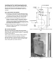
SECTION 6 FOUR-WIRE GROUND FAULT OPTION The ground fault option for four-wire installations requires the installation of an additional current sensor on the neutral bus in the equipment. The sensor is connected to the trip unit through the connector provided in the wiring harness. Installing the Fourth-Wire Disconnect AK-50 & AKS-50 Stationary Breakers The fourth-wire disconnect for stationary breakers consists of a terminal board mounted to the lower front channel, as shown in Figure 24.
AK-50 & AKS-50 Draw-Out Breakers The fourth-wire disconnect for AK-50 and AKS-50 draw-out breakers mounts to the lower back frame, as shown in Figure 25. • If the terminal board is already present on the breaker, just replace the control harness. Maintain the following color code: white wire to common, black wire to the tap. • If the disconnect must be added, mount it as shown in Figure 25. AK-75 & AK-100 Draw-Out Breakers Figure 25. Fourth-wire disconnect installed on AK-50 & AKS-50 draw-out breakers.
Figure 28. AK-75 & AK-100 back frame conversion.
Installing the Neutral Sensor The neutral sensor is an electrical duplicate of the phase sensor, including the taps. Therefore, when taps (if provided) are changed on the phase sensors, the taps on the neutral sensor must be similarly changed. For kits with fixed phase sensors, be sure to use the corresponding tap on the neutral sensor. Mount the neutral sensor on the outgoing neutral lead, normally in the equipment bus or cable compartment.
Figure 30.
SECTION 7. EQUIPMENT CONVERSION Installing Mounting Brackets The equipment compartment contains the mating portions of the fourth-wire disconnect and the neutral sensor. The same disconnect assembly is used for types AKD, AKD-5, and AKD-6 switchgear. Mounting brackets for AKD, AKD-5, AKD-6, and AKD-8 switchgear applications are included in the conversion kit. Figures 31, 32, 33, 34, and 35 are mounting diagrams for the various applications.
Figure 34. AK-50 & AKS-50 fourth-wire disconnect for AKD. Figure 35. Fourth-wire disconnect for AKD-5 & AKD-6.
SECTION 8. TESTING AND TROUBLESHOOTING ter or millivolt tester. If the resistance differs considerably from phase to phase, the electrical connections may not be properly tightened or it could also indicate improper contact wipe. 4. To verify that the breaker has been properly retrofitted, perform a primary injection test on each phase. This test will check the CTs, bus, wiring harness, flux shifter, and trip unit as a complete system. a.
connecting the breaker from all power sources, perform the following procedure: Breaker 1. Check that all phase sensors are the same type (current range). 2. Verify that the tap settings on all three phase sensors are identical. 3. Verify that the wiring harness connections to the sensors have the proper polarity (white lead to common, black lead to tap), as shown in the cabling diagram in Figure 36. 4.
Figure 36. Cabling diagram for ProTrip™ trip units with ground fault on four-wire loads.
APPENDIX – DRILL TEMPLATES Appendix 1.
Appendix 2. Drill Template for Trip Unit Mounting Appendix 3.
These instructions do not cover all details or variations in equipment nor do they provide for every possible contingency that may be met in connection with installation, operation, or maintenance. Should further information be desired or should particular problems arise that are not covered sufficiently for the purchaser’s purposes, the matter should be referred to the GE Company. g GE Industrial Systems General Electric Company 41 Woodford Ave.