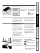
Range Hoods GE Appliances Safety Information . . . . . . . . . 3 Owner’s Manual and Installation Instructions Operating/Care and Cleaning Instructions Charcoal Filters . . . . . . . . . . . . .5 Grease Filters . . . . . . . . . . . . . . .4 Hood Lights . . . . . . . . . . . . . . . .5 Hood Surfaces . . . . . . . . . . . . . .5 Stainless Steel Surfaces . . . . . . .5 Vent Controls . . . . . . . . . . . . . . .4 JV535 JV536 JV565 JV566 JV635 JV636 JV665 JV666 Installation Instructions . . . . . . . . . .
Safety Instructions GE & You, A Service Partnership. IMPORTANT! Fill out the Consumer Product Registration Card. Two easy ways to register your appliance! ■ Through the internet at www.geappliances.com ■ Complete and mail the enclosed Product Registration Card Operating Instructions FOR YOUR RECORDS Write the model and serial numbers here: # # You can find them on a label on the back wall of the hood. Staple sales slip or cancelled check here.
SAFETY PRECAUTIONS WARNING – TO REDUCE THE RISK OF CAUTION – For general ventilating use only. Do not use to exhaust hazardous or explosive materials and vapors. WARNING – TO REDUCE THE RISK OF RANGE TOP GREASE FIRE: A. Never leave surface units unattended at high settings. Boilovers cause smoking and greasy spillovers that may ignite. Heat oils slowly on low or medium settings. B. Always turn hood ON when cooking at high heat or when cooking flaming foods. C. Clean ventilating fans frequently.
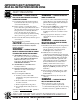
Safety Instructions Using the hood controls. Throughout this manual, features and appearance may vary from your model. Customer Service Installation Instructions Operating Instructions Your model will have one of the above type of controls. FAN Control LIGHT Control Turn or press (according to your model) the FAN speed control to LO, MED, HI or BOOST, as needed. Turn or press (according to your model) the LIGHT control to BRIGHT for bright light while cooking.
The charcoal filters are clipped inside of each reusable metal grease filter. The charcoal filters cannot be cleaned. They must be replaced. For 30″ hood models, order Kit no. WB02X10707. For 36″ hood models, order Kit no. WB02X10708. These kits can be ordered from your GE supplier. If the model is not vented to the outside, the air will be recirculated through disposable charcoal filters that help remove smoke and odors.
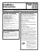
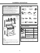
Range Hood Installation Instructions Models JV535 JV635 JV536 JV636 JV565 JV665 JV566 JV666 Questions? Visit our Website at: www.geappliances.com or Call GE Answer Center at 800.626.2000 BEFORE YOU BEGIN DUCTWORK REQUIREMENTS Read these instructions completely and carefully. NOTE: Read the ductwork sections only if you do not have existing ductwork. If you have existing ductwork, skip to the “Damage” section and proceed. • IMPORTANT – Save these instructions for local inspector’s use.
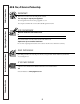
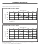
Installation Instructions Follow the guidelines for proper duct sizing in the ducting charts. DUCTING CHART–JV5 Series Models Equivalent Length in Feet Air Volume in CFM 250 0 25 • • 200 50 75 • • 100 • • 150 31⁄4″ x 10″ Rectangular 125 150 7″ Round • • • 100 125 • 100 31⁄4″ x 10″ Rectangular Transition to 6″ Round = 4.5 ft. 7″ Round 90° Elbow = 8 ft. 7″ Roof Cap = 30 ft.
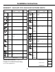
Installation Instructions WORKSHEET – CALCULATE TOTAL EQUIVALENT DUCTWORK LENGTH DUCT PIECES EQUIVALENT NUMBER LENGTH x USED = TOTAL 31⁄4″ x 10″ Rect., straight 1 Ft. 7″ Round, straight 1 Ft. 6″ Round, straight 1 Ft. 31⁄4″ x 10″ Rect. 90° elbow 8.5 Ft. x ( ) = Ft. 31⁄4″ x 10″ Rect. 45° elbow 7 Ft. x ( ) = Ft. 31⁄4″ x 10″ Rect. 90° flat elbow 24 Ft. x ( ) = Ft. 31⁄4″ x 10″ Rect. wall cap with damper 45 Ft. (7 ft. w/o damper) x ( ) = Ft. x ( ) = Ft. 31⁄4″ x 10″ Rect.
Installation Instructions DAMAGE – SHIPMENT/INSTALLATION TOOLS YOU WILL NEED • If the unit is damaged in shipment, return the unit to the store in which it was bought for repair or replacement. • If the unit is damaged by the customer, repair or replacement is the responsibility of the customer. • If the unit is damaged by the installer (if other than the customer), repair or replacement must be made by arrangement between customer and installer.
Installation Instructions 1 CHOOSE VENT OPTION The outside vent exhaust option that your installation requires will determine the hood knockouts that you will use. If the hood is to be installed in a recirculating, nonvented ductless manner, do not knock out any vent openings in the hood. Only an electrical access hole will be knocked out of the hood. NOTE: Only JV5 Series models may be recirculated. We do not recommend the recirculated configuration for JV6 Series models.
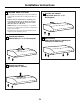
Installation Instructions 2 REMOVE EXHAUST ADAPTOR 5 REMOVE OTHER EXHAUST ADAPTOR Remove the 7″ round exhaust adaptor from the top of the hood. Set it aside along with its mounting screws. Remove the 31⁄4″ x 10″ rectangular exhaust adaptor from inside the hood. Set it aside along with its mounting screws and parts bag. Depending on the model, the exhaust adaptor will be located on the left or right side.
Installation Instructions 10 FOR 31⁄4″ X 10″ RECTANGULAR 8 REMOVE DUCT KNOCKOUT(S) If recirculating, non-vented ductless (optional for JV5 Series models only), see note below and skip to Step 12 D and proceed. We do not recommend the recirculated configuration for JV6 Series models. Using a flat blade screwdriver, remove the appropriate duct knockout(s) from the top or back of the hood. 31⁄4″ x 10″ Rectangular vertical discharge. Remove top rectangular duct knockout only.
Installation Instructions D.Recirculating (non-vented ductless– Available on JV5 Series models only) 12 MARK HOLES Select the vent option that your installation will require and proceed to that section: • Use the hood as a template and mark the locations on the cabinet for the electrical wiring and keyhole screw slots. • Since the hood is to be recirculated (not to be vented outside), do not cut out any vent openings in the wall or cabinet bottom. A.
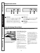
Installation Instructions 22 CONNECT WIRING 18 SECURE HOOD Connect house black to hood black wire, house white to hood white wire, and house ground under green ground screw. Securely tighten the strain relief clamp onto the house wiring. Slide the hood back against the wall. Tighten the mounting screws. Be sure the screw heads are in the narrow neck of the keyhole slot. Green ground screw Mounting screw (4) Keyhole (4) NOTE: DO NOT PUSH ON FAN BLADE.
All warranty service provided by our Factory Service Centers or an authorized Customer Care® technician. For service, call 800-GE-CARES. For The Period Of: GE Will Replace: One Year From the date of the original purchase Any part of the range hood which fails due to a defect in materials or workmanship. During this full one-year warranty, GE will also provide, free of charge, all labor and in-home service to replace the defective part.
Safety Instructions Service Telephone Numbers. GE Answer Center ® 800.626.2000 The GE Answer Center® is open 24 hours a day, 7 days a week. OR Visit our Website at: www.geappliances.com In-Home Repair Service 800-GE-CARES (800-432-2737) Operating Instructions Expert GE repair service is only a phone call away. Special Needs Service 800.626.2000 800-TDD-GEAC (800-833-4322) GE offers, free of charge, a brochure to assist in planning a barrier-free kitchen for persons with limited mobility.