Custom Hood Insert Safety Information . . . . . . . . . .2, 3 Warranty . . . . . . . . . . . . . . . . . . . . . . . . 4 Owner’s Manual and Installation Instructions Assistance / Accessories . . . . . . 5 JVC3300 Hood Using The Hood Controls . . . . . . . . . . . . . . . . . . . . . . . . . . . 6 Filters . . . . . . . . . . . . . . . . . . . . . . . . . . . . . . 7 Care and Cleaning Surfaces . . . . . . . . . . . . . . . . . . . . . . . . . . . 8 Lights . . . . . . . . . . . . . . . . . . . . . . .
SAFETY INFORMATION IMPORTANT SAFETY INFORMATION. READ ALL INSTRUCTIONS BEFORE USING. This is the safety alert symbol. This symbol alerts you to potential hazards that can kill or hurt you and others. All safety messages will follow the safety alert symbol and the word “DANGER”, “WARNING”, or “CAUTION”. These words are defined as: DANGER Indicates a hazardous situation which, if not avoided, will result in death or serious injury.
WARNING TO REDUCE THE RISK OF A RANGE TOP GREASE FIRE: A. Never leave surface units unattended at high settings. Boilovers cause smoking and greasy spillovers may ignite. Heat oils slowly on low or medium settings. B. Always turn hood ON when cooking on high heat or when flambéing food (i.e. Crepes Suzette, Cherries Jubilee, Peppercorn Beef Flambé). C. Clean ventilating fans frequently. Grease should not be allowed to accumulate on fan or filter. D. Use proper pan size.
WARRANTY Thank You! ... for your purchase of a GE Brand appliance. Register Your Appliance: Register your new appliance on-line at your convenience! www.geappliances.com/service_and_support/register/ Timely product registration will allow for enhanced communication and prompt service under the terms of your warranty, should the need arise. You may also mail in the pre-printed registration card included in the packing material. GE Warranty GEAppliances.
Try the GE Appliances Website (www.geappliances.com/service_and_support/) 24 hours a day, any day of the year! For greater convenience and faster service, you can now download Owner’s Manuals, order parts or even schedule service on-line. Schedule Service: Expert GE repair service is only one Real Life Design Studio: GE supports the Universal step away from your door. Get on-line and schedule your Design concept of products, services and environments service at www.geappliances.
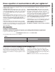
USING THE HOOD: Controls Controls 1 0 1 1. Light Switch: 0 is OFF. Move switch to 1 for ON. 2. Blower Switch: 0 is OFF. Move switch to 1 for LOW speed, 2 for MEDIUM speed, and 3 for HIGH speed. The pilot lamp illuminates when the blower switch is set to 1, 2, or 3. 6 Pilot Lamp 2 0 1 2 3 Heat Sensor Your hood is equipped with a HEAT SENSOR thermostat. This thermostat is a device that will turn on or speed up the blower if it senses excessive heat above the cooking surface. 1.
Be sure the circuit breaker is off and all surfaces are cool before cleaning or servicing any part of the vent hood. Metal Grease Filter The metal filters trap grease during cooking. The filter must ALWAYS be in place when the hood is in use. The grease filter is dishwasher-safe and should be cleaned every 6 months, or as needed. Wire Retainers To remove: Remove the access panel by sliding the two side latches. Remove the wire retainers and then remove the grease filter.
CARE AND CLEANING: Surfaces/Lights Surfaces Painted Surfaces Do not use a steel wool pads or other abrasive cleaners; they will scratch the surface. Clean grease-laden surfaces of the hood frequently. To clean the hood surface, use a hot, damp cloth with a mild detergent suitable for painted surfaces. About one tablespoon of ammonia may be added to the water. Use a clean, hot, damp cloth to remove soap. Dry with a dry, clean cloth.
Installation Instructions Custom Hood Insert JVC3300 Hood “If you have questions, call 800.GE.CARES (800.432.2737) or visit our website at: GEAppliances.com” BEFORE YOU BEGIN Read these instructions completely and carefully. IMPORTANT • — Save these instructions for local inspector’s use. • — Observe all governing codes and ordinances. Note to Installer – Be sure to leave these instructions with the Consumer. Note to Consumer – Keep these instructions for future reference.
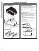
INSTALLATION PREPARATION Installation Preparation PRODUCT DIMENSIONS INSTALLATION CLEARANCES This vent hood and liner assembly must be installed 24" required minimum and 36" recommended maximum above the cooking surface. • Always refer to the cooktop or range installation instructions for product-specific clearances. NOTE: Installation height should be measured from the cooking surface to the bottom edge of the metal hood liner or cabinet surface.
ADVANCE PLANNING Recirculation Install Planning Duct Install Planning A recirculation duct kit JXN30 is available for recirculation installation. • This hood is designed to be vented vertically through the ceiling. Use a 6" round duct. Use locally supplied elbows to vent horizontally through the rear wall. • Use metal ductwork only. • Determine the exact location of the vent hood. • Plan the route for venting exhaust to the outdoors. To maximize the ventilation performance of the vent system: 1.
INSTALLATION PREPARATION Installation Preparation TOOLS AND MATERIALS REQUIRED (NOT SUPPLIED) Needle-nose pliers Electric drill and appropriate bits Aluminized duct tape Silicone Pencil and tape measure Step ladder Safety glasses Spirit level 6" ducting and caps as needed Flashlight Tin snips Wire cutter/ stripper PARTS PROVIDED Gloves Phillips and flatblade screwdrivers PLAN THE INSTALLATION Locate the parts packed with the hood.
PREPARE FOR CABINET INSTALLATION PREPARE FOR ISLAND INSTALLATION 1. Insert the damper assembly into the hood 1. Insert the damper assembly into the hood exhaust duct. exhaust duct. 2. The hood should be centered left to right over the cooktop. NOTE: The exhaust duct on the hood is closer to the rear of the hood. It is important to plan for the alignment to the connection point of the hood. 2. The hood should be centered left to right over the cooktop.
INSTALLATION Installation STEP 1 INSTALL HOOD LINER (If Used) STEP 2 INSTALL THE HOOD (Cont) 1. The rectangular opening in framing or custom cabinet must be sized for the liner outside and inside dimensions. Refer to Product Dimensions section. 2. Secure the liner with the 4 screws that are provided with the liner. 3. Fasten with 4 screws. There is a spring locking clip on one side of the hood to assist with holding one side up while installing the screws.
INSTALLATION Installation STEP 3 RECIRCULATION KIT (If Used) 1. Cut a hole into the soffit for the exhaust duct. 2. Install the vent grill over the exhaust duct. 3. Seal the duct joints with duct tape. Soffit Cutout Hood Center Line 90° Angle Boot CL 10-1/4" 6" Round to 7" Round Transition 25" Combination Filter Liner STEP 4 FINALIZE INSTALLATION 1. 2. 3. 4. 49-80778 Plug in the hood. Install the access panel. Check operation of the lights and blower. Finish the custom cabinetry.
TROUBLESHOOTING TIPS 16 Troubleshooting tips ... Before you call for service Save time and money! Review the charts on the following pages first and you may not need to call for service. Problem Possible Cause What To Do Fan/Light does not operate when slide switch is turned ON A house fuse may be blown or a circuit breaker tripped. Replace fuse or reset circuit breaker. Loud or abnormal airflow noise Wrong duct size used in installation. This hood requires 6” ducting to perform optimally.
Hotte Encastrable Et Adaptable Renseignements de sécurité . . . . . . . . . . . . . . 2, 3 Manuel du propriétaire et instructions d’installation Garantie. . . . . . . . . . . . . . . . . . . . . 4 Hotte JVC3300 Assistance / Accessoires . . . . . 5 Utilisation de la hotte Commandes . . . . . . . . . . . . . . . . . . 6 Filtres. . . . . . . . . . . . . . . . . . . . . . . . 7 Entretien et nettoyage Des surfaces. . . . . . . . . . . . . . . . . . 8 Lampes . . . . . . . . . . . . . . . . . . . . . .
RENSEIGNEMENTS DE SÉCURITÉ RENSEIGNEMENTS DE SÉCURITÉ IMPORTANTS. LISEZ TOUTES LES INSTRUCTIONS AVANT L’UTILISATION. Ce symbole représente une alerte de sécurité. Ce symbole vous avise de dangers possibles pouvant causer la mort, des blessures ou autres. Tous les messages de sécurité seront précédés du symbole d’alerte de sécurité ainsi que des mots « DANGER », « AVERTISSEMENT » ou « MISE EN GARDE ».
AVERTISSEMENT RÉDUISEZ LE RISQUE D’UN FEU DE GRAISSE SUR LA SURFACE DE CUISSON DU FOUR : A. Ne laissez jamais sans surveillance les unités de cuisson de surface à une température élevée. Le bouillonnement occasionne des débordements fumants et graisseux qui peuvent prendre feu. Chauffez à feu doux les substances huileuses, avec un réglage bas ou moyen. B. Mettez toujours la hotte en marche si vous cuisez à température élevée ou préparez des mets flambés (p.ex.
GARANTIE Merci! ... pour votre achat d'un électroménager de marque GE. Enregistrez votre électroménager : Enregistrez votre nouvel appareil en ligne au moment qui vous convient le mieux! www.geappliances.com/service_and_support/register/ L’enregistrement de votre produit dans les délais prescrits permet une meilleure communication et un service rapide, selon les modalités de votre garantie, si besoin est.
Visitez le site des électroménagers GE (www.geappliances.com/service_and_support/) 24 heures par jour, à n’importe quel jour de l’année! Une façon pratique et rapide d’obtenir un service : télécharger des manuels d’utilisation, commander des pièces et même planifier une réparation en ligne. Service planifié : Le service de réparation expert GE n’est qu’à un pas de votre porte. Connectez-vous et programmez votre réparation sur le www.geappliances.com/service_and_support/ ou composez le 800.GE.CARES (800.432.
UTILISATION DE LA HOTTE : Commandes Commandes 1 0 1. 2. 6 Lampe témoin 1 Interrupteur de la lampe : 0 pour ÉTEINDRE. Basculez à 1 pour ALLUMER. Commutateur du ventilateur : 0 pour ARRÊT. Placez à 1 pour la vitesse BASSE, 2 pour la vitesse MOYENNE et 3 pour la vitesse ÉLEVÉE. La lampe témoin s’allume lorsque le commutateur du ventilateur est placé à 1, 2 ou 3. 2 0 1 2 3 Capteur de chaleur Votre hotte est équipée d’un thermostat à CAPTEUR DE CHALEUR.
Assurez-vous que le disjoncteur est désarmé (OFF) et que toutes les surfaces sont refroidies avant de nettoyer ou réparer toute pièce de la hotte. Filtre à graisse métallique Les filtres métalliques retiennent la graisse pendant la cuisson. Le filtre doit TOUJOURS être en place lorsque la hotte fonctionne. Le filtre à graisse va au lave-vaisselle et doit être nettoyé tous les 6 mois, ou au besoin Broches de retenue Pour enlever : Retirez le panneau d’accès en glissant les deux loquets latéraux.
ENTRETIEN ET NETTOYAGE : Surfaces/Lampes Surfaces Surfaces peintes N’utilisez pas de tampons en laine d’acier ni d’autres nettoyants abrasifs; ils vont rayer la surface. Nettoyez les surfaces graisseuses de la hotte fréquemment. Pour nettoyer la surface de la hotte, utilisez un linge doux imbibé d’eau chaude et de détergent doux qui convient aux surfaces peintes. On peut ajouter environ une cuillerée à table d’ammoniac à l’eau. Utilisez un linge doux imbibé d’eau chaude pour essuyer le savon.
Hotte encastrable et adaptable Hotte JVC3300 « Pour toute question, composez le 800.GE.CARES (800.432.2737) ou visitez notre site Web : GEAppliances.com » AVANT DE COMMENCER Veuillez lire toutes ces instructions attentivement. • IMPORTANT — Conservez ces instructions à l’usage de l’inspecteur local. • • • • • • IMPORTANT — Observez tous les codes et décrets en vigueur. Note à l’installateur – Assurez-vous de laisser ces instructions au consommateur.
PRÉPARATION DE L’INSTALLATION Préparation de l’installation DIMENSIONS DU PRODUIT DÉGAGEMENTS DE L’INSTALLATION Cet assemblage hotte-jupe doit être installé à un minimum de 24 po et un maximum recommandé de 36 po au-dessus de la surface de cuisson. • Reportez-vous toujours aux instructions d’installation de la table de cuisson ou de la cuisinière pour connaître les dégagements spécifiques d’un produit.
PLANIFICATION AVANCÉE Planification d’une installation avec recyclage d’air Planification de l’installation des conduits • Cette hotte est conçue pour être ventilée verticalement à travers le plafond. Utilisez un conduit rond de 6 po. Utilisez des coudes achetés localement pour ventiler horizontalement à travers le mur arrière. • Utilisez des conduits métalliques seulement. • Déterminez l’emplacement exact de la hotte. • Planifiez la trajectoire de la ventilation d’évacuation vers l’extérieur.
PRÉPARATION DE L’INSTALLATION Préparation de l’installation OUTILS ET MATÉRIAUX REQUIS (NON FOURNIS) Pince à becs pointus Crayon et ruban à mesurer Perceuse électrique et forets appropriés Ruban pour conduits aluminisés Silicone Escabot Lunettes de sécurité Niveau Lampe de poche Cisaille Pince à couper/ dénuder les fils PIÈCES FOURNIES Conduits et capuchons de 6 po selon besoins Gants Tournevis à pointe étoilée ou plate PLANIFIER L’INSTALLATION Repérez les pièces emballées avec la hotte.
PRÉPARATION DE L’INSTALLATION DE L’ARMOIRE PRÉPARER L’INSTALLATION AU-DESSUS D’UN ÎLOT 1. Insérez le registre dans le conduit d’évacuation de la hotte. 1. Insérez le registre dans le conduit d’évacuation de la hotte. 2. La hotte doit être centrée de gauche à droite au-dessus de la table de cuisson. REMARQUE : Le conduit d’évacuation sur la hotte est plus près de l’arrière de la hotte. Il est important de planifier l’alignement au point de raccordement de la hotte. 2.
INSTALLATION Installation ÉTAPE 1 INSTALLER LA JUPE DE HOTTE (s’il y a lieu) 1. L’orifice rectangulaire dans l’armature ou l’armoire sur mesure doit être découpé en fonction des dimensions extérieure et intérieure de la jupe. Reportez-vous à la section Dimensions du produit. 2. Fixez la jupe à l’aide des 4 vis fournies avec la jupe. ÉTAPE 2 INSTALLER LA HOTTE (suite) 3. Fixez à l’aide des 4 vis.
INSTALLATION Installation ÉTAPE 3 ENSEMBLE DE RECYCLAGE D’AIR (s’il y a lieu) 1. Découpez un orifice dans le soffite pour le conduit d’évacuation. 2. Posez la grille de ventilation par-dessus le conduit d’évacuation. 3. Scellez les joints avec du ruban pour conduits. Découpe du soffite Découpe du soffite CL Boîtier de raccordement à 90° 10-1/4" Raccord de transition 6 po rond à 7 po rond 25" Filtre combiné Jupe ÉTAPE 4 FINALISER L’INSTALLATION 1. Branchez la hotte dans la prise électrique. 2.
CONSEILS DE DÉPANNAGE 16 Conseils de dépannage ... Avant de faire un appel de service Économisez temps et argent! Consultez les tableaux des pages suivantes en premier lieu pour vous épargner un appel de service. Problème Cause probable Correctif Le ventilateur/la lampe ne fonctionne pas lorsque le commutateur coulissant est à la position ON (Marche). Un fusible du domicile est grillé ou le disjoncteur s’est déclenché. Remplacez le fusible ou réarmez le disjoncteur.
Inserción para Campana Estándar Información De Seguridad .2, 3 Garantía . . . . . . . . . . . . . . . . . . . . . . . . . 4 Asistencia / Accesorios . . . . . . . . 5 Uso de la Campana Manual del propietario e Instrucciones de Instalación JVC3300 Pirámide Controles . . . . . . . . . . . . . . . . . . . . . . . . . . 6 Filtros . . . . . . . . . . . . . . . . . . . . . . . . . . . . . . 7 Cuidado Y Limpieza Superficies . . . . . . . . . . . . . . . . . . . . . . . . . 8 Luces . . . . . . . . . . . . . . .
INFORMACIÓN DE SEGURIDAD INFORMACIÓN IMPORTANTE DE SEGURIDAD LEA TODAS LAS INSTRUCCIONES ANTES DE USAR Éste es el símbolo de alerta de seguridad. El mismo alerta sobre potenciales riesgos que le pueden producir la muerte o lesiones tanto a usted como a otras personas. Todos los mensajes de seguridad estarán a continuación del símbolo de alerta de seguridad y con la palabra “PELIGRO”, “ADVERTENCIA” o “PRECAUCIÓN”.
ADVERTENCIA PARA REDUCIR EL RIESGO DE UN INCENDIO DE GRASA SOBRE UNA ESTUFA: A. Nunca deje unidades de superficie desatendidas en configuraciones de calor elevadas. Los alimentos que hierven y se derraman provocan humo y derrames grasosos que pueden prenderse fuego. Caliente los aceites lentamente en configuraciones bajas o medias. B. Siempre encienda el sistema de ventilación cuando cocine con configuraciones de calor elevadas o cuando flambee alimentos (por ej.
GARANTÍA ¡Gracias! ... por su compra de un electrodoméstico de la Marca GE Registre su Electrodoméstico: ¡Registre su electrodoméstico nuevo a través de Internet, según su conveniencia! www.geappliances.com/service_and_support/register/ Un registro puntual de su producto permitirá una mejor comunicación y un servicio más puntual de acuerdo con los términos de su garantía, en caso de surgir la necesidad.
¡Consulte el Sitio Web de Electrodomésticos de GE (www.geappliances.com/service_and_support/) durante las 24 horas, cualquier día del año! Para mayor conveniencia y un servicio más rápido, ahora puede descargar el Manual del Propietario, ordenar piezas o incluso programar el servicio técnico a través de Internet. Servicio Programado: El servicio de reparación de expertos de GE está a sólo un paso de su puerta. Entre a Internet y programe su servicio en www.geappliances.
USO DE LA CAMPANA: Controles Controles 1 0 1. 2. 6 Lámpara Piloto 1 Interruptor de Luz: 0 es OFF (Apagado). Mueva el interruptor a 1 para activar la función ON (Encender). Interruptor del Calefactor: 0 es OFF (Apagado). Mueva el interruptor a 1 para velocidad BAJA, 2 para velocidad MEDIA, y 3 para velocidad ALTA. La lámpara piloto ilumina cuando el interruptor del calefactor está configurado en 1, 2 o 3. 0 2 1 2 3 Sensor de Calor Su campana está equipada con un termostato con SENSOR DE CALOR.
Asegúrese de que la energía eléctrica esté apagada y que todas las superficies estén frías antes de limpiar o arreglar cualquier pieza de la campana de ventilación. Filtro de grasa metálico Los filtros metálicos atrapan la grasa durante la cocción. Filtro debe estar SIEMPRE en su lugar cuando la campana esté en funcionamiento. El filtro de grasa es apto para lavavajillas y debe limpiarse cada 6 meses, o según sea necesario. Para quitar: Retire el panel de acceso deslizando los dos pestillos laterales.
CUIDADO Y LIMPIEZA: Superficies/Lámparas Superficies Superficies Pintadas No use virutas de acero u otros limpiadores abrasivos; estos rayarán la superficie. De forma frecuente, limpie las superficies sucias de grasa. Para limpiar la superficie de la campana, use una tela caliente y húmeda con un detergente suave adecuado para superficies pintadas. Se puede agregar aproximadamente una chuchara sopera de amoníaco al agua. Use una tela limpia, caliente y húmeda para eliminar el jabón.
Instrucciones de instalación Inserción para Campana Estándar JVC3300 Hood ¿Preguntas? Llame al 800.GE.CARES (800.432.2737) o visite nuestro sitio Web en: GEAppliances.com ANTES DE COMENZAR Lea estas instrucciones por completo y con detenimiento. • IMPORTANTE ³ Guarde estas instrucciones para el uso de inspectores locales. • • • • • • • IMPORTANTE ³ Cumpla con todos los códigos y ordenanzas vigentes. Nota al instalador – Asegúrese de dejar estas instrucciones con el Consumidor.
PREPARACIÓN PARA LA INSTALACIÓN Preparación para la instalación DIMENSIONES DEL PRODUCTO ESPACIOS PARA LA INSTALACIÓN This vent hood and liner assembly must be installed 24" required minimum and 36" recommended maximum above the cooking surface. • Siempre consulte las instrucciones de instalación de la estufa o cocina en relación a los espacios específicos del producto.
PLANIFICACIÓN PREVIA Planificación para la Instalación con Conducto • Esta campana está diseñada para ventilarse en forma vertical a través del cielorraso. Use un conducto circular de 6”. Utilice codos suministrados en forma local para ventilación horizontal a través de la pared trasera. • Use tuberías metálicas únicamente. • Determine la ubicación exacta de la campana de ventilación. • Planifique el recorrido de la salida de ventilación hacia el exterior.
PREPARACIÓN PARA LA INSTALACIÓN Preparación para la instalación HERRAMIENTAS Y MATERIALES REQUERIDOS (NO SE SUMINISTRAN) Alicates de punta larga Perforadora eléctrica y brocas correspondientes Cinta aislante de aluminio Silicona Lápiz y cinta métrica Step ladder Gafas de seguridad Nivel de burbuja de aire Conductos de 6" y tapas según sea necesario Linterna Tijeras para hojalata Alicate pelacables Guantes Destornilladores de estrella y de lados planos PIEZAS PROVISTAS PLAN DE INSTALACIÓN Ubique
PREPARACIÓN PARA LA INSTALACIÓN DEL GABINETE PREPARACIÓN PARA LA INSTALACIÓN DE LA ISLA 1. Inserte el ensamble 1. Inserte el ensamble del regulador en el conducto de salida de la campana. del regulador en el conducto de salida de la campana. 2. La campana debe estar centrada de izquierda a derecha sobre la superficie de cocción. 9/16" NOTA: El conducto de salida de la campana está más cerca de la parte trasera de la campana.
INSTALACIÓN Instalación PASO 1 INSTALACIÓN DEL COBERTOR DE LA CAMPANA (Si se Usa) 1. La abertura rectangular de la estructura o del gabinete estándar debe ser acorde con las dimensiones internas y externas del cobertor. Consulte la sección de Dimensiones del Producto. 2. Asegure el cobertor con los 4 tornillos que fueron provistos con el cobertor. PASO 2 INSTALACIÓN DE LA CAMPANA (Cont.) 3. Ajuste con 4 tornillos.
INSTALACIÓN Installation PASO 3 KIT DE RECIRCULACIÓN (Si se Usa) 1. Haga un agujero en el sofito para el conducto de salida. 2. Instale la parrilla de ventilación sobre el conducto de salida. 3. Selle las uniones del conducto con cinta para conductos. Corte del Sofito Línea central de la campana Bota en Ángulo de 90º CL 10-1/4" Transición del Conducto Redondeado de 6" a 7" 25" Filtro de Combinación Cobertor PASO 4 FINALICE LA INSTALACIÓN 1. Enchufe la campana. 2. Instale el panel de acceso. 3.
CONSEJOS PARA LA SOLUCIÓN DE PROBLEMAS 16 Consejos para la Solución de Problemas... Antes de solicitar el servicio técnico ¡Ahorre tiempo y dinero! Primero revise los cuadros que aparecen en las siguientes páginas y es posible que no necesite solicitar reparaciones. Problema Causas posibles Qué hacer El ventilador/luz no funciona cuando el interruptor está en ON (Encender). El fusible puede haberse quemado o el interruptor decircuitos puede haber saltado.