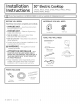
Installation 30” Electric Cooktop Instructions CP350, JP340, JP346, JP356, PP912, PP932, PP942, PP944, PP945, PP950 “lf you have questions, call 800.GE.CARES or visit our website at: GEAppliances.com” BEFORE YOU BEGIN MATERIALS YOU WILL NEED Read these instructions completely and carefully. °IM PO RTANT — save these instructions for local inspector's use. ¢ IMPORTANT — observe al governing codes and ordinances. ¢ Note to Installer - Be sure to leave these instructions with the Consumer.
Installation Instructions IMPORTANT SAFETY INSTRUCTIONS FOR YOUR SAFETY ELECTRICAL REQUIREMENTS e For Personal Safety, remove house fuse or open circuit breaker before beginning installation. Failure to do so could result in serious injury or death. e Be sure your cooktop is installed properly by a qualified installer or service technician. e To eliminate the risk of burns or fire due to reaching over heated surface elements, cabinet storage located above the surface units should be avoided.
Installation Instructions PRE-INSTALLATION CHECKLIST Remove Installation Instructions from literature pack and read them carefully before you begin. A WARNING -— the electrical power to the cooktop supply line must be shut off while connections are being made. Failure to do so could result in serious injury or death. When preparing cooktop opening, make sure the inside of the cabinet and the cooktop do not interfere with each other. (See section on preparing the opening.
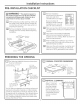
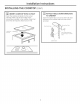
Installation Instructions PREPARING THE OPENING (cont) [4] CUTOUT DIMENSIONS [6] For Americans with Disabilities Act (ADA) OF THE COUNTERTOP Forward Approach Installation Only: To insure accuracy, it is best to make a template when cutting the opening in the counter. 28-1/2" E—~_ length of 1-3/4" Min. Between cutout and the wall cut behind the cooktop / 2-1/2" Min.
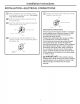
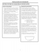
Installation Instructions INSTALLING THE COOKTOP [4] INSTALLING THE JUNCTION BOX [3 | ATTACH FOAM TAPE Install an approved junction box where it will be Apply the foam tape around the outer edge of the glass. Do not overlap the foam tape. easily reached through the front of the cabinet where the cooktop will be located. The cooktop conduit is 3 feet long. Bottom of Cooktop mo \ a Cooktop Glass Note: On CP350S, PP912S, PP932S, PP942S, PP9O4AS, Install junction box so that it can be reached through t
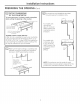
Installation Instructions INSTALLING THE COOKTOP (CONT,) [6] INSERT COOKTOP INTO CUTOUT Insert the cooktop centered into the cutout opening. Make sure the front edge of the countertop is parallel to the cooktop. Make final check that all required clearances are met. [7] ATTACH HOLD DOWN TO CABINET BRACKETS Open the cabinet door and screw the hold down brackets to the cabinet sides with the screws provided.
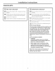
Installation Instructions INSTALLATION—ELECTRICAL CONNECTIONS When making the wire connections, use the entire length of conduit provided. The conduit must not be shortened. [—] Once the connections are made, secure wires together using wire nuts. Red With the cooktop in place, open the front of the cabinet door. Strain Relief Clarnp Insert the wires from the conduit through the opening of the junction box.
Installation Instructions CHECKLISTS [4] PRE-TEST CHECKLIST [2] OPERATION CHECKLIST Remove all protective film, if present, and any Remove all items from the top of the cooktop stickers. surface. Check to be sure that all wiring is secure and Turn on the power to the cooktop.(Refer to not pinched or in contact with moving parts. your Owner's Manual.) Verify that all surface burners operate properly. Check level of appliance. [bo] Check that the cooktop is properly grounded.
Instrucciones Estufa eléctrica de 30" de instalacion CP350, JP340, JP346, JP356, PP912, PP932, PP942, PP944, PP945, PP950 “Si tiene alguna pregunta, llame al 800.GE.CARES 0 visite nuestro sitio Web en: GEAppliances.com” NECESITARA LOS SIGUIENTES MATERIALES ANTES DE COMENZAR Lea estas instrucciones por completo y con cuidado. ° IM PO RTANTE — Conserve estas instrucciones para el uso del inspector local. ¢ IMPORTANTE — Cumpla con todos los cédigos y reglas aplicables.
Instrucciones de instalacion INSTRUCCIONES DE SEGURIDAD IMPORTANTES PARA SU SEGURIDAD REQUISITOS ELECTRICOS e Para su seguridad personal, retire los fusibles de su hogar o bien abra el cortacircuitos antes de comenzar con la instalacion. El no hacerlo puede resultar en lesiones serias 0 incluso la muerte. e Asegurese que su estufa sea instalada correctamente por un instalador o técnico de servicio calificado.
Instrucciones de instalacion LISTA DE VERIFICACION PREVIA A LA INSTALACION Saque las instrucciones de A ADVERTENCIA = La corriente eléctrica a la tuberia de abastecimiento de la estufa debe cortarse durante la realizaci6n de conexiones. El EASY INSTALLATION OF YOUR NEW 30" COOKTOP instalaci6n del paquete de material impreso y léalas cuidadosamente antes de comenzar. Asegurese de colocar todo el material impreso, Manual de propietario, instalaciones, etc., en un lugar seguro para referencia futura.
Instrucciones de instalacion PREPARACION DE LA ABERTURA (cont [4] DIMENSIONES DEL AREA CORTADA EN EL MOSTRADOR Para garantizar la precisidn, es mejor crear una [6] Instalacién Por Delante Unicamente de Acuerdo con la Ley de Estadounidenses con Incapacidades (ADA) plantilla al momento de cortar la abertura en el mostrador. 19-5/8" ancho del corte 28-1/2" : 1-3/4" Min.
Instrucciones de instalacion INSTALACION DE LA ESTUFA [7] INSTALACION DE LA CAJA DE EMPALMES Instale una un lugar de gabinete en El conducto caja de empalmes aprobada en facil acceso a través del frente del donde pueda colocarse la estufa. de la estufa tiene 4 pies de longitud. [3] APLIQUE LA CINTA DE ESPUMA Aplique la cinta de espuma alrededor del borde externo del vidrio. No aplique un exceso de cinta de espuma. Parte inferior de la estufa OO LAMA LL Al LLL Lilia SSNs on \ A Cinta de espuma a Vi
Instrucciones de instalacion INSTALACION DE LA ESTUFA (CONT,) [6] INSERTE LA ESTUFA EN EL AREA CORTADA [7] SUJETE LAS ABRAZADERAS DE MONTAJE AL GABINETE Inserte la estufa centrada en el Grea cortada. Asegurese de que el borde frontal del mostrador esté paralelo con respecto a la estufa. Asegurese de verificar al final que todos los espacios especificados hayan sido respetados. Abra la puerta del gabinete y atornille las abrazaderas de montgje a los lados del gabinete con los tornillos incluidos.
Instrucciones de instalacion INSTALACION—CONEXIONES ELECTRICAS Cuando realice las conexiones de cables, [|] Una vez que se hayan realizado las utilice toda la extension del conducto incluido. El conducto no debe reducirse. conexiones, fije los cables con las tuercas para cables. Con la estufa colocada en su lugar, abra el frente de la puerta del gabinete. Inserte los cables del conducto a través de la abertura de la caja de empalmes.
Instrucciones de instalacion LISTAS DE VERIFICACION [7] LISTA DE VERIFICACION PREVIA Retire toda la pelicula protectora, si la hay, [2] LISTA DE VERIFICACION DE OPERACION y las calcomanias. Retire todos los objetos que se encuentren Verifique que todos los cables estén fijos y que sobre la superficie de la estufa. no estén torcidos o en contacto con partes moviles. Encienda (Consulte que todas funcionen Verifique el nivel del aparato.