Installation Instructions If you have questions, call 800.GE.CARES or visit our website at: www.monogram.
Safety Information READ AND SAVE THESE INSTRUCTIONS BEFORE YOU BEGIN Read these instructions completely and carefully. • IMPORTANT ³ Save these instructions for local inspector’s use. • IMPORTANT ³ Observe all governing codes and ordinances. • Note to Installer ³ Be sure to leave these instructions with the Consumer. • Note to Consumer ³ Keep these instructions with your Owner’s Manual for future reference. • Skill Level ³ Installation of this appliance requires basic mechanical and electrical skills.
Consignes de Sécurité LISEZ ET CONSERVEZ CES INSTRUCTIONS AVANT DE COMMENCER Lisez ces instructions entièrement et attentivement. IMPORTANT • ³ Conservez ces instructions pour l’inspecteur électrique local. • IMPORTANT ³ Respectez tous les codes et règlements en vigueur. • Remarque pour l’installateur – Assurez–vous de remettre ces instructions à l’utilisateur. • Remarque pour l’Utilisateur – Conservez ces instructions avec votre notice d’utilisation pour toute référence future.
Installation Instructions CONTENTS Product Dimensions .............................................................................. 4 Installation Clearances ........................................................................ 5 Optional Duct Cover Accessories .................................................... 5 Determine Installation Height, Duct Cover Accessories ......6 Advance Planning .................................................................................. 7 Power Supply .............
Advance Planning INSTALLATION CLEARANCES These vent hoods are designed to be installed onto a wall RU EHQHDWK D VRI¿W RU FDELQHW • Install these hoods* 30" Min. to 36" Max. above the cooking surface. *These hoods may be installed 24" min. above a gas or electric drop-in style cooktop. Always observe the 30" to 36" clearance when installed over any professional style cooktop or range. Note: Clearances may vary due to type of cooking product and local codes.
Advance Planning DETERMINE INSTALLATION HEIGHT, DUCT COVER ACCESSORIES These vent hoods must be installed 30” min. to 36” max. above the standard 36” high cooking surface when installed over any professional style rangetop or range. The exact hood installation height is determined by the ceiling height. Measure the exact ceiling height. Review the chart at right to determine the range of possible hood installation heights that can be accomplished with one or more duct covers. 3.
Advance Planning ADVANCE PLANNING Ductwork Planning • These vent hoods are equipped for 10" round ductwork. For best performance, use 10" round ductwork on the 48" wide hoods. 30" and 36" hoods may be transitioned to 8" round. • This hood may be vented vertically through upper FDELQHWV VRI¿W RU FHLOLQJ $ GXFW WUDQVLWLRQ SLHFH LV supplied for vertical exhaust. Use locally supplied elbows to vent horizontally through the rear wall. • Determine the exact location of the vent hood.
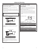
Advance Planning DUCT FITTINGS Quantity Used Use this chart to compute maximum permissable lengths for duct runs to outdoors. 10" round to 8" round 5 ft. Note: Do not exceed maximum permissable equivalent lengths! Round, straight 1 ft. (per foot length) Maximum recommended duct OHQJWK IRU WKHVH KRRGV IHHW 3-1/4" x 10" 3-1/4" x 12" straight 1 ft. (per foot length) 90° elbow 8" Dia. 17 ft. 10" Dia. 24 ft. 45° elbow 8" Dia. 10 ft. 10" Dia. 14 ft.
Installation Preparation TOOLS AND MATERIALS REQUIRED (NOT SUPPLIED) Hammer Duct tape Pencil and tape measure Electric or battery operated drill and 1/8", 3/8" bits Key Hole Saw Wire cutter/ stripper Safety glasses 10" round metal duct, length to suit installation. Wire nuts Spirit level 3KLOOLSV DQG ÀDW blade screwdrivers Flashlight Pliers Metal Snips Strain relief for junction cover. Step ladder 120V 60Hz. 15 or 20 Amp, 2-wire with ground. Properly grounded branch circuit.
Installation Preparation PARTS PROVIDED Locate the parts packed with the hood. Wood Support with Original Screws Duct Transition with Damper 2 Stainless Steel Grease Filters ¿OWHUV ZLWK PRGHOV Heat Lamp (2 with 48" models) Allen Wrench For Implement Rods HARDWARE PACKAGE Locate and check contents. Screws shown actual size.
Installation Instructions 67(3 '(7(50,1( +22' '8&7:25. $1' :,5,1* /2&$7,216 • Use a level to draw the cooktop centerline location. Draw the line to ceiling height. • Measure desired distance from the bottom of the hood to the cooking surface, 30" min. to 36" max. Note: If you are installing the hood with duct covers, be sure to read “Using Duct Cover Accessories” page 7. Exact installation height may be determined by use of one or more duct covers.
Installation Instructions 67(3 $ ,167$// +22' 2172 :$// SKIP THIS STEP IF INSTALLING BENEATH A SOFFIT OR CABINET, *2 72 67(3 % IMPORTANT: Framing must be capable of VXSSRUWLQJ XS WR OEV Install Transition Onto Top of Hood • Locate at least 2 vertical studs at the wood support. • Center the supplied wood support, left to right and below the 15-3/8" marked line. Duct Transition IMPORTANT: Remove shipping tape from damper and check that damper moves freely.
Installation Instructions 67(3 % $OWHUQDWH 0RXQWLQJ 0HWKRG INSTALL HOOD TO SOFFIT OR BENEATH CABINETS SKIP THIS STEP IF USING WALL MOUNTING METHOD When necessary, the hood may be installed so that it is VXSSRUWHG E\ WKH VRI¿W 7KH VRI¿W VKRXOG EH FRQVWUXFWHG ZLWK [ ·V • Determine the installation location on the wall.
Installation Instructions STEP 3 CONNECT DUCTWORK 67(3 ,167$// '8&7 &29(56 • Install ductwork, making connections in direction of DLUÀRZ DV LOOXVWUDWHG • Secure joints in ductwork with sheetmetal screws. • Wrap all duct joints with duct tape for an airtight seal. 8VH GXFW WDSH WR VHDO WKH ÀDQJH FRQQHFWLRQ 5HDFK inside the hood and push the damper up to be sure it moves freely.
Installation Instructions STEP 7 INSTALL FILTERS STEP 8 INSTALL IMPLEMENT RODS 3ODFH ¿OWHU GULS WUD\V LQWR WKH UHDU RI WKH KRRG Screw Stand-offs Into Hood Use Allen Wrench to Secure Rod to Stand-offs ,QVHUW WKH JUHDVH ¿OWHU LQWR WKH RSHQLQJ DQG GURS LQWR the trays. 7R UHPRYH WKH ¿OWHUV JUDVS WKH KDQGOH SXVK WKH ¿OWHU up and lift out. 8VH D ÀDW EODGH VFUHZGULYHU WR LQVWDOO VWDQG RIIV LQWR WKH bottom of the hood.
Note: While performing installations described in this book, safety glasses or goggles should be worn. For Monogram® local service in your area, call 1.800.444.1845. Note: Product improvement is a continuing endeavor at General Electric. Therefore, materials, appearance and VSHFL¿FDWLRQV DUH VXEMHFW WR FKDQJH ZLWKRXW QRWLFH 49-80151-8 02-13 GE Printed in Mexico GE Consumer & Industrial GE Appliances General Electric Company Louisville, KY 40225 GEAppliances.