
User manual


10
Follow these steps to place the 4x4 Matrix for HDMI 1.3 into IR channel setup
mode.
1. Remove the power cable from the rear side of the 4x4 Matrix for HDMI 1.3
2. Press and hold the front panel RESET button while re-inserting the power
cable to enter the setup mode. All output LED banks will be active except for
Output 1 which will display the currently selected IR channel.
3. Note the IR channel used on the RMT-16IR remote and press the RESET
button to cycle to the IR channel that matches.
4. Reset the unit by removing and re-inserting the power cable from the rear
panel. Changes will be active when this is complete.
1 2 1 2
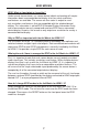
Left: Picture of the opened rear battery
compartment of the RMT-16IR remote showing
the exposed DIP Switch bank between the
battery chambers.
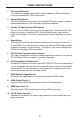
Output-1
1
Channel 1
234
Output-1
1
Channel 2
234
Output-1
1
Channel 3
234
Output-1
1
Channel 4
234
Channel 1:
Default
1 2
1
2
Channel 3:
Channel 2:
1 2
1
2
Channel 4:
How to Resolve IR Code Confl icts
In the event that IR commands from other remote controls confl ict with the
supplied RMT-16IR remote control, changing the remote channel will alleviate
this issue. The RMT-16IR remote control has a bank of DIP switches for
confi guring the remote channel that both units use to communicate. The 4x4
Matrix for HDMI 1.3 can be put into a mode that will uses its front LED array to
indicate which remote channel is being used and also give the user the ability
to modify the currently used IR remote channel. These IR channel settings must
exactly match each other for proper operation.
The DIP Switch bank on the RMT-16IR is located underneath the battery cover.
IR CHANNEL CONFIGURATION