
User manual

5
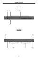
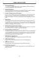
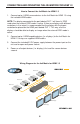
1 IR (Infrared) Receiver
This receiver will accept command for switching between HDMI input devices
using the included RMT-16IR remote control.
2 Power LED Indicator
This LED will become active once the included 5V DC power supply is properly
connected between the unit and a open wall power receptacle.
3 Display 1-4 Selected Input LED Indicator
There is a set of 4 LEDs for each of the four output ports. Each of the four LED
output sets contain 4 individual LED’s that will indicate which input source is
active for that output. The currently selected input will be indicated by an active
LED.
4 Reset Button
This button will reset the unit and force all devices in the chain to re-transmit/
re-read EDID. It is essential that the unit be reset after the EDID mode has been
changed (see page 7 for more details). This button is also used to confi gure the
IR channel (see page 10 for more details).
5 RS-232 Serial Communications Interface
This input is provided for switching and advanced feature control via an external
RS-232 device. Please see page 11 for more information.
6 IR (Infrared) Receiver Extension
An optional IR Receiver Extension (part # EXT-RMT-EXTIR) can be connected if
the unit is placed in a location that will not provide line of sight to the included IR
remote control. The IR extension can then be placed in a location where it can
receive commands form the IR remote control.
7 EDID Selection Toggle Button
This button will toggle between the internal and external EDID modes.
8 HDMI Output Ports 1-4
Connect up to 4 HDMI capable devices to these HDMI output ports.
9 HDMI Input Ports 1-4
Connect up to 4 HDMI source devices to these HDMI input ports.
10 5V DC Power Input Port
Connect the included 5V DC power supply between this port and an open wall
power receptacle.
PANEL DESCRIPTIONS