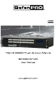
080P
ASKING FOR ASSISTANCE Technical Support: Telephone (818) 772-9100 (800) 545-6900 Fax (818) 772-9120 Technical Support Hours: 8:00 AM to 5:00 PM Monday through Friday, Pacific Time Write To: Gefen, LLC c/o Customer Service 20600 Nordhoff St Chatsworth, CA 91311 www.gefenpro.com support@gefenpro.com Notice Gefen LLC reserves the right to make changes in the hardware, packaging and any accompanying documentation without prior written notice.
CONTENTS 1 2 3 4 5 6 7 8 8 9 9 9 10 11 11 12 12 13 14 15 16 17 18 19 20 21 22 23 23 24 27 28 30 30 31 32 33 34 35 36 37 38 39 Introduction Operation Notes Features Front Panel Layout Front Panel Descriptions Back Panel Layout Back Panel Descriptions Connecting the 16x16 3GSDI Push Button Matrix Wiring Diagram Operating the 16x16 3GSDI Push Button Matrix The Standby Screen Displaying Additional Information Displaying the Current Routing State Mode Buttons Routing Sources System Lock Mode Standby Mode Cyclin
INTRODUCTION Congratulations on your purchase of the 16x16 3GSDI Push Button Matrix. Your complete satisfaction is very important to us. Gefen Gefen delivers innovative, progressive computer and electronics add-on solutions that harness integration, extension, distribution and conversion technologies.
OPERATION NOTES READ THESE NOTES BEFORE INSTALLING OR OPERATING THE 16X16 3GSDI PUSH BUTTON MATRIX • There is no internal scaling in the 16x16 3GSDI Push Button Matrix. All of the attached monitors must be able to display the resolutions output by the source devices. For maximum compatibility it is recommended that only one compatible/common resolution be used by all of the source devices. • Routing features can be accessed using the serial control interface.
FEATURES Features • Supports resolutions up to 1080p, 1920x1200, and 2K. • Front panel control buttons for local switching. • Serial interface for remote control via a computer or control automation devices supports RS-232 and RS-485 protocols.
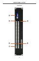
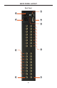
FRONT PANEL LAYOUT 6 1 2 5 3 4 Front Panel 4
FRONT PANEL DESCRIPTIONS Front Panel 1 Mode Buttons These buttons are used to control other features on the product. See pages 11 17 for more information. 2 Output Buttons (1 - 16) Used for routing an Input to an Output. Each of these buttons represents an Output. See page 11 for more information on routing 3GSDI sources. 3 Power Indicator This LED indicator will glow red when the power is turned on.
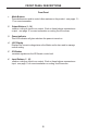
BACK PANEL LAYOUT 9 1 8 2 3 4 7 6 5 Back Panel 6
BACK PANEL DESCRIPTIONS Back Panel 1 Reference In Connector Connect an external reference to this connector. Bi-level (black burst) and trilevel sync are supported. 2 3G-SDI Output Ports (1 - 16) Connect 3G-SDI monitors to these ports. 3 Grounding Terminal Provides a discharge path to ground in case a short circuit occurs between the “hot” lead of the power supply and the enclosure of the Matrix. The grounding wire should be attached from the grounding terminal to an approved ground path.
CONNECTING THE 16X16 3GSDI PUSH BUTTON MATRIX How to Connect the 16x16 3GSDI Push Button Matrix 1. Connect up to 16 3G-SDI source devices to the 3G-SDI inputs on the rear panel of the 16x16 3GSDI Push Button Matrix using SDI cables. 2. Connect up to 16 3G-SDI displays to the 3G-SDI outputs on the rear panel of the 16x16 3GSDI Push Button Matrix. 3. Connect the included power cord to the power input receptacle on the rear panel of the 16x16 3GSDI Push Button Matrix.
OPERATING THE 16X16 3GSDI PUSH BUTTON MATRIX The Standby Screen The front panel of the 16x16 3GSDI Push Button Matrix has a 16 character 2 line LCD display. This display will shows the current routing status of the Matrix and will be used to perform routing commands and other operations.
OPERATING THE 16X16 3GSDI PUSH BUTTON MATRIX Displaying the Current Routing State 1. To display the current routing status of the Matrix, press any one of the Input or Output buttons on the front panel. Input buttons Output buttons 2. The current routing state of any output or input will be indicated by glowing blue buttons on the front panel: In the example above, Input 8 (bottom row) is routed to Output 5, Output 7, and Output 12 (top row).
MODE BUTTONS Routing Sources 1 To change the current routing state, press Set Button to activate Routing Mode. Press the Set button 2 Press the desired Output button. One or more Output buttons may be selected. Input buttons Output buttons 3 Press any Input on the bottom row of buttons (1 - 16), corresponding to the source to be displayed on the output(s). 4 Press the Set button to complete the operation. The system will remain in Routing Mode.
MODE BUTTONS System Lock Mode Locking the Matrix prevents changes to any of the Matrix settings. This feature is useful in case any of the front panel buttons are pressed by accident. Locking the Matrix also prevents changes using the IR Remote Control Unit. 1 Press the Lock button to activate System Lock Mode. Press the Lock button 2 Press the Lock button a second time to deactivate System Lock Mode. Standby Mode 1 Press the Cancel button, while in any mode, to return to the Standby Mode screen.
MODE BUTTONS Cycling between Information Screens Press the Cancel button, while in Status Check Mode, to cycle through the Information Screens.
MODE BUTTONS Saving the current Routing State 1 Set the routing state (see page 11), then press the PreSet button twice to activate Preset Mode. Press PreSet button twice 2 Press an Input button (1 - 16) to store the current routing state. Select the Input 3 Press the Set button to complete the operation. The system will remain in Save Current Preset Mode.
MODE BUTTONS Recalling a stored Routing State 1 Press the PreSet button once to activate Recall Preset Mode. Press PreSet button twice 2 Press the Input button (1 - 16) of the routing state to be recalled. Select the Input 3 Press the Set button to complete the operation. The system will remain in Recall Saved Set Mode.
MODE BUTTONS Masking Outputs Masking prevents the output device (display, etc) from receiving an output signal, instead of powering-down the output device. The masking process is identical for masking or unmasking outputs. 1 Press the Mask button to activate Mask Mode. Press the Mask button 2 Select the Output to be masked. Select the Output 3 Press the Set button to complete the operation.
MODE BUTTONS Communication Modes The Comm button allows the Matrix to switch between RS-232 and RS-485 (EIA485) modes. 1 Press the Comm button to activate the Communications Mode. The current communication method (RS232) will be displayed.
IR REMOTE CONTROL DESCRIPTIONS RMT-16416IR Remote Control Unit 1 2 1 Activity Indicator This LED will be glow yellow each time a button is pressed. 2 Display and Source Selection Buttons (1 - 16) These buttons are used to select which source is routed to a monitor. NOTE: An Activity Indictor that flashes quickly while holding down any one of the sixteen buttons indicates a low battery. Replace the IR Remote Control battery as soon as possible.
IR REMOTE CONTROL INSTALLATION Installing the RMT-16416IR Battery 1. Remove the battery cover on the back of the IR Remote Control unit. 2. Insert the included battery into the open battery slot. The positive (+) side of the battery should be facing up. 3. Replace the battery cover. The Remote Control unit ships with two batteries. One battery is required for operation and the other battery is a spare. Battery Slot WARNING: Risk of explosion if battery is replaced by an incorrect type.
IR REMOTE CONTROL CONFIGURATION How to Resolve IR Code Conflicts In the event that IR commands from other remote controls interfere with the supplied IR Remote Control unit, changing the IR channel on the IR Remote Control unit will fix the problem. The IR Remote Control unit has a bank of DIP switches used for setting the IR channel. The DIP switch bank is located underneath the battery cover.
USING THE IR REMOTE CONTROL IR Remote Control Key Mapping Each input and output on the 16x16 3GSDI Push Button Matrix is represented by a button on the IR Remote Control unit. The table below lists the corresponding inputs and outputs. Remote Button Monitor / Source 1 1 2 2 3 3 4 4 5 5 6 6 7 7 8 8 9 9 10 10 11 11 12 12 13 13 14 14 15 15 16 16 Routing Sources using the IR Remote Control unit Issuing a routing command is a two step process.
RS-232 SERIAL INTERFACE What features are available via the RS-232 serial communications port? p The 16x16 3GSDI Push Button Matrix can accept commands through the RS-232 serial communications port located on the rear panel. The current RS-232 control features are: • Switching/routing of inputs to outputs without the RMT-16416IR remote control. How do I use these features? These features were initially intended for utilization by custom installers in automated setups.
RS-232 SERIAL CONTROL RS-232 Features RS-232 remote commands are used to control this product’s features. Features include input / output routing and reference signal commands . These features are available only through the use of the serial port. Command Syntax y The syntax for each command is always the same: #Command name → Space ( _ ) as command name end flag → Parameter 1 → Space → Parameter 2 → Parameter n → Carriage Return ( \r ) → Sample: #CommandName_param1_param2_param3_param4...
RS-232 SERIAL CONTROL #PRREFTABLE Command The #PRREFTABLE command displays the Ref In data table (timings) which are recognized by the 16x16 3GSDI Push Button Matrix.
RS-232 SERIAL CONTROL #RSTIP Command The #RSTIP command sets the current IP configuration to factory (default) settings. Syntax y : #RSTIP Parameters: None Notes: A reboot is required after using this command. #SIPADD Command The #SIPADD command specifies a new IP address.
RS-232 SERIAL CONTROL #SNETMASK Command The #SNETMASK command specifies a new net mask. Syntax y : #SNETMASK param1 param2 param3 param4 Parameters: param1 IP address [0 - 255] param2 IP address [0 - 255] param3 3 IP address [0 - 255] param4 IP address [0 - 255] Notes: A reboot is required after using this command. #SGATEWAY Command Specifies the new IP gateway.
RS-232 SERIAL CONTROL #SPORT Command Specifies a new port. Syntax y : #SPORT param1 Parameters: param1 Port [0 - 255] Notes: A reboot is required after using this command. General Commands Command Description #ACTIVEBOLO Enables the boot loader #FADEFAULT Sets all routing states to default settings #RMTIRADD Set the remote IR channel #ACTIVEBOLO Command The #ACTIVEBOLO command enables the boot loader.
RS-232 SERIAL CONTROL #FADEFAULT Command The #FADEFAULT command sets all routing states to default (1 - 1, 2 - 2, 3 - 3, etc). Syntax y : #FADEFAULT Parameters: None #RMTIRADD Command The #RMTIRADD command sets the remote IR channel.
RS-232 SERIAL CONTROL R Command The R command allows specific routing of inputs and outputs. Syntax y : r param1 param2 Parameters: param1 3GSDI Ouput [1 - 16] param2 3GSDI Input [1 - 16] S Command The S command routes a single input to all 16 3GSDI outputs. Syntax y : s param1 Parameters: param1 Input [1 - 16] Notes: Setting param1 to a value of 0 will place the matrix in one-to-one mode. This means that Input1 will be routed to Output1, Input2 will be routed to Output2, and so on.
IP CONTROL The GefenPRO 16x16 3GSDI Push Button Matrix supports IP-based control using an integrated Web interface. To access this feature, an IP address, subnet, gateway, and port number need to be set on the 16x16 3GSDI Push Button Matrix (Default IP: 192.168.0.70 Subnet: 255.255.255.0 Gateway: 192.168.0.1 Port: 80). Consult the network administrator to obtain the proper IP address and settings for this product to properly communicate on the network.
IP CONTROL Masking The Masking page is used to hide an output from displaying any video. From this page, all outputs can be set to “Active” or “Mask”. When an output is set to “Active”, it will command normally. When an output is set to “Mask”, it will not output any video. To set the “Active” or “Mask” mode, follow the steps below. 1. Select either “Active” or “Mask” for any number of desired outputs. 2. Press the “Submit” button to initiate the change(s).
IP CONTROL IP Configuration The IP Configuration page is used to set the IP settings that will be used to access the Web interface. The following items can be configured from this menu. • IP Address (Default: 192.168.0.70) • Subnet (Default: 255.255.255.0) • Gateway (192.168.0.1) • Port (Default: 80) • • To change these settings follow the steps below. 1. Enter the desired network information into the fields provided. 2. Press the “Save” button to initiate the change(s).
IP CONTROL Backup / Restore The Backup/Restore page is used to backup and restore setup configurations. Note: This feature will be implemented in a future release.
FIRMWARE UPDATE Firmware Update Follow the on-screen instructions to complete the firmware update process: 1. Using Hyperterminal, enter the #ACTIVEBOLO command twice. 2. Press [1] on the computer keyboard to begin downloading program to the temporary memory. 3. A message will appear in Hyperterminal: Waiting for the file to be sent ... (press ‘a’ to abort) 4. In Hyperterminal, click Transfer > Send File... 5. Click Browse... and select the .BIN file to be uploaded (e.g. 3GSDI16X16_ uIP_2_1.
WARNING MESSAGES System Failure In the case of a critical malcommand, the following warning message will be displayed on the Main Display: If the 16x16 3GSDI Push Button Matrix is connected to a PC using a terminal program, the following message will appear on the display: System failure !!! Power-down the Matrix immediately and contact Gefen Technical Support. See Asking for Assistance at the beginning of this manual.
RACK MOUNT SAFETY INFORMATION a. Maximum recommended ambient temperature: 45 ˚C (104 ˚F). b. Increase the air flow as needed to maintain the recommended temperature inside the rack. c. Do not exceed maximum weight loads for the rack. Install heavier equipment in the lower part of the rack to maintain stability. d. Connect a bonding wire between an approved safety ground and the grounding screw on the chassis.
SPECIFICATIONS Input / Output • SDI (SMPTE 259MI up to 360 Mbps) • HD-SDI (SMPTE 292M up to 1.485 Gbps) • 3G-SDI (SMPTE 424M/425M up to 3.0 Gbps) Supported Formats......................................................All SD, HD, and 3G formats Maximum Resolution...........................................................1080p, 1920x1200, 2K Input / Output Connector-type..........................................................................BNC Input / Output Impedance.................................
WARRANTY Gefen warrants the equipment it manufactures to be free from defects in material and workmanship. If equipment fails because of such defects and Gefen is notified within two (2) years from the date of shipment, Gefen will, at its option, repair or replace the equipment, provided that the equipment has not been subjected to mechanical, electrical, or other abuse or modifications.
LICENSING lwIP is licenced under the BSD licence: Copyright (c) 2001-2004 Swedish Institute of Computer Science. All rights reserved. Redistribution and use in source and binary forms, with or without modification, are permitted provided that the following conditions are met: 1. Redistributions of source code must retain the above copyright notice, this list of conditions and the following disclaimer. 2.
Rev A1 Pb