® POWER SYSTEMS, INC. H-100 Control Panel Technical Manual This manual should remain with the unit.
IMPORTANT SAFETY INSTRUCTIONS H-100 Control Panel Technical Manual SAVE THESE INSTRUCTIONS – The manufacturer suggests that these rules for safe operation be copied and posted in potential hazard areas. Safety should be stressed to all operators and potential operators of this equipment. Study these SAFETY RULES carefully before installing, operating, or servicing this equipment. Become familiar with this manual and all literature pertaining to the generator set and related equipment.
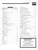
Table of Contents H-100 Control Panel Technical Manual Table of Contents The Event Log ............................................................... 23 Safety Rules ........................................ Inside Front Cover Maintenance Settings .................................................... 24 General Information ......................................................... 2 Air/Fuel Ratio Control (Option) ..................................... 24 Introduction ...................................
General Information H-100 Control Panel Technical Manual INTRODUCTION The H-100 Control Panel is an electronic control box that functions as an advanced standby generator controller. Its technology is based on the flagship PMDCP system with all its flexibility included. A familiar user interface in the form of GenLink®-DCP is used to program, monitor and change the parameters in the unit. The interface appears the same as it does for the PM-DCP.
General Information H-100 Control Panel Technical Manual THE MEASUREMENT "ENGINE" ANALOG MATHS The measurement “engine” is the key feature of the system. All the inputs to the controller are processed by this module. Each physical input is measured and the result processed by an individual set of rules that are set via a PC and GenLink.
General Information H-100 Control Panel Technical Manual Where x can be: Setpoints 1. THERMISTOR 2. CURRENT 3. LINEAR 4. PRESSURE 5. UNALTERED 6. POLY_3RD 7. POLY_2ND 8. POLY_1ST 9. POLY_1ST_N1 10. POLY_1ST_N2 11. CAL_SCALE 12. CFM_SENSOR 13. GEN_FP_POLY The function x may use any of the coefficients 1,2,3 and in some cases will use calibration factor as a 4th coefficient (in this case use scaling factor for calibration).
General Information H-100 Control Panel Technical Manual IMMEDIATE = Alarms/Warnings with this qualification only become active immediately after the engine has started. Sensor Failure Check When this field is set, the input sensor is checked for short circuit or open circuit failure. Normally each of the inputs are conditioned externally to be 420mA current loops. Any currents outside this range indicate a sensor failure. This will cause an alarm to occur.
General Information H-100 Control Panel Technical Manual ENGINE MANAGEMENT The engine management module is very similar to that used in the manufacturer's other products. It controls engine cranking, engine starting, engine running and engine stopping. These functions are performed to a set of “rules” that can be customized via parameters from GenLink. In turn, the module needs to know certain things about the engine which it expects to be programmed in from GenLink.
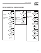
General Information H-100 Control Panel Technical Manual STARTING AND STOPPING - SEQUENCE DIAGRAMS NO 2-wire Remote Starting and Stopping Sequence Keyswitch in Auto Position NOTE: Shutdown Alarms will cause the engine to turn off or not start. Exercise without transfer starting and stopping sequence keyswitch in auto position.
General Information H-100 Control Panel Technical Manual VOLTAGE REGULATOR (OPTION) All panels include automatic voltage regulation as standard. There are various settings that can be made to the voltage regulator via GenLink. The settings are normally factory preset and are shown here for completeness. • Voltage KP/KI/KD — Voltage regulation stability constants. • PMG — YES indicates a Permanent Magnet Excited alternator. • VF Corner 1 / 2.
General Information H-100 Control Panel Technical Manual • Dump Enable — Indicates if extra load dump governor compensation is desired to reduce increase in frequency caused by drop in load. The following three selections are available: - No Dump — No additional compensation. - Dump — Reset governor algorithm when load dump detected. - Dump & Hold — Same as Dump, but also hold throttle closed until frequency back in range.
General Information H-100 Control Panel Technical Manual LOCAL TRENDING No Trigger Local trending is done inside the controller where up to 1000 samples can be stored in memory. GenLink provides an interface to select the analog channels to be trended, the rate to be sampled at, and optional triggers to be used to specify when to sample. Up to 6 analog channels can be sampled. However, the 1000 samples are divided by the number of channels.
General Information H-100 Control Panel Technical Manual Generator control is limited to the following output options (referred to as “Hooks”). 1. Use Keyswitch 2. Force Off – cleared with “Use Keyswitch” hook 3. Force Manual – cleared with “Use Keyswitch” hook 4. Force Auto – cleared with “Use Keyswitch” hook 5. Force Dialout 6. Halt ILC 7. Force Alarm/Warning #1 8. Force Alarm/Warning #2 9. Force Remote Start For detail in programming the ILC, refer to the ILC manual. field.
General Information H-100 Control Panel Technical Manual > Volts < LINE 1: “Transfer Switch Name” indicates which switch inputs are being displayed such as “From HTS #1”. To select a switch to display, select the switch number on the HTS page (refer to the Right Display Pages - Exercise/HTS page).
General Information H-100 Control Panel Technical Manual > Power < Press the “MENU” button: This is a typical System Power page. Use the arrow keys to move the cursor to the desired menu item and then press the “ENTER” button. Most menu items have multiple pages under them. When that is the case, there is a “More (x-y)” field at the lower right hand corner of the page where “x” is the page number and “y” is the total number of pages available under this menu item.
General Information H-100 Control Panel Technical Manual Press the “ENTER” button. This is a typical System Alarm and Warning page. The n/a indicates there is not an alarm or warning to display on that line. As depicted, this display indicates a Fuel Pressure alarm for low pressure. This would be a common alarm for a system that has the gas line turned off. The “Al” indicates it is an alarm. The “*” indicates the alarm has not been acknowledged.
General Information H-100 Control Panel Technical Manual This is a typical second engine parameter page. The first two values on this page are not able to be configured as other values. LINE 1: Engine RPM LINE 2: Battery Voltage in Volts DC. If any of these signals are not configured, they will display “n/a” for their value. Press the button. LINE 3: Normally Battery Charger Current (Analog Channel #9). If it is not configured, the line will be blank. LINE 4: “More” field to allow page selection.
General Information H-100 Control Panel Technical Manual STATUS There are two System Status pages. These pages show the system status, system time, and system versions. Do the following to view the system status pages: Press the “MENU” button. The engine is starting or running because the GenLink commanded it to start and the key switch is in the AUTO position. “Running exercise” The engine is starting or running because internal exercise was activated and the key switch is in the AUTO position.
General Information H-100 Control Panel Technical Manual “Warmed Up, Alarms On” SERVICE Generator is started, warmed up, and the hold-off alarms are enabled. There are four Maintenance Status pages. The first three pages show the status of the scheduled maintenance items. The fourth page allows changing of the display contrast. “Running,cooling down” Generator is still running, but waiting for cool down timer to expire. “Stopping” Do the following to view the service pages: Press the “MENU” button.
General Information H-100 Control Panel Technical Manual Each line displays a maintenance item that has been set up via GenLink. The value displayed is the approximate % of life remaining before maintenance should be performed. Refer to the Maintenance setup using GenLink. Press the “ENTER” button. Press the button and then the button. This is a typical third Maintenance Status page. Each line displays a maintenance item that has been set up via GenLink.
General Information H-100 Control Panel Technical Manual This is a typical first Generator Parameter page for a single phase system. LINE 1: Phase titles for the voltage and current – voltage title/current title. LINE 2: Line-to-Line voltage for AB and Line-toNeutral voltage for A and B in Volts RMS. LINE 3: Neutral current and Line currents in Amps RMS. LINE 4: Generator frequency in Hz followed by the “More” field to allow page selection. Press the “ENTER” button.
General Information H-100 Control Panel Technical Manual This is a typical first System Diagnostics page. It displays ten of the discrete inputs into the H-100 Control Panel. Inputs to the controller are internally pulled to 5 v, so to activate an input you must short it to ground.
General Information H-100 Control Panel Technical Manual Press the “ENTER” button. Press the button. Press the “ENTER” button. Press the “ENTER” button. The above two pages are typical of communications diagnostics, one page for each port. The LCD display will show four lines of information about the port: This is a typical first Internal Exercise and HTS page. LINE 1: Will show the type of port protocol that has been selected.
General Information H-100 Control Panel Technical Manual HTS is in Time Delayed Neutral position. “Synching” HTS is waiting for Generator and Utility to become synchronized before changing switch position. “SB4 Xfer” HTS has activated the “Signal Before Transfer” relay. “Cls Gen SW” This is a typical third Internal Exercise and HTS page. LINE 1: The left side shows the HTS switch number that the data on this page applies to. This field is editable in that switch numbers 1 – 4 can be selected.
General Information H-100 Control Panel Technical Manual page also selects the switch to use for the Left Display Switch Mimic diagram if that switch is enabled. In addition, it is the selected switch number for the previous page, and for the remote annunciator lights for generator power and line power. The right side of the first line is the enable state of the HTS. It is editable and can have the following values: “Disabled” This HTS switch is not included in the system.
General Information H-100 Control Panel Technical Manual The event log, as its name implies, is designed to store events which are programmable from GenLink. Each measurement channel or output function can be set as an event along with a setpoint. For example, if you set Digital Input #1 (the keyswitch in AUTO position) as an event with a setpoint of logical one, each time the keyswitch is set in the auto position, an event will be logged.
General Information H-100 Control Panel Technical Manual INTERNAL EXERCISE FUNCTION Generators best maintain their readiness by being exercised once per week. This prevents the machine from stagnating and provides an opportunity to discover any maintenance items that may need service before the unit is actually needed for emergency power.
General Information H-100 Control Panel Technical Manual Select the day of week to run the exercise. Select the time of day to run exercise. Click on “QuietTest®” to enable the exercise mode with reduced sound levels. Press “Apply”. Click on ”Select Exercise” to enable internal exercise and allow the changing of the other exercise parameters. Setup of QuietTest® is now complete.
General Information H-100 Control Panel Technical Manual QUIETTEST® SETUP USING FRONT PANEL Press the “MENU” button. Select the time of day to run exercise. Move the cursor using the arrow keys to the Exercise/ HTS menu item. Press the “ENTER” button. Verify “QuietTest®” is not checked. Press “Apply”. Setup of Normal exercise is now complete.
General Information H-100 Control Panel Technical Manual Use the up and down arrow keys until a “Y” appears in the field. Press the “ENTER” button to exit edit mode. Move the cursor to the “Time Start” day of week field on the second line. Press the “ENTER” button to enter edit mode. Press the "ENTER" button to exit edit mode. Move the cursor to the “Time Start” time of day hours field on the second line. Press the “ENTER” button to enter edit mode.
General Information H-100 Control Panel Technical Manual Move the cursor to the “Time Start” time of day minutes field on the second line. Move the cursor to the “QuietTest Selected” field on the first line. Press the “ENTER” button to enter edit mode. Press the “ENTER” button to enter edit mode. Use the up and down arrow key until the desired minute of the hour is displayed. Use the up and down arrow key until a “Y” appears. Press the “ENTER” button to exit edit mode.
General Information H-100 Control Panel Technical Manual Setup of QuietTest® is now complete. For this example, QuietTest® will start every Wednesday at 10:30 AM and run until about 10:50 AM While QuietTest® is running, the “Time Remaining” will display the approximate number of minutes left before QuietTest® is completed. Press the “ENTER” button to enter edit mode. NORMAL EXERCISE SETUP USING FRONT PANEL Press the “MENU” button. Use the up and down arrow keys until a “Y” appears in the field.
General Information H-100 Control Panel Technical Manual NOTE: In a number field the up/down arrows move the digit up and down while the left/right arrows move to the adjacent digit. Use the up and down arrow key until the desired day of the week is displayed. Press the “ENTER” button to exit edit mode. Press the "ENTER" button to exit edit mode. Move the cursor to the “Time Start” time of day minutes field on the second line.
General Information H-100 Control Panel Technical Manual Press the “ENTER” button to exit edit mode. Use the up and down arrow key until a “N” appears. Move the cursor to the on the bottom line. Press the “ENTER” button to exit edit mode. Press the “ENTER” button to move to the second page. Setup of Normal Exercise is now complete.
General Information H-100 Control Panel Technical Manual DATE AND TIME SETUP USING GENLINK Connect to the H-100 control panel. Use the up and down arrow key until a “Y” appears. Press the “ENTER” button to exit edit mode. The date and time field is displayed in the lower left corner of the screen. Using the mouse cursor, click on the date and time field. Setup of Normal Exercise with transfer to load during exercise is now complete.
General Information H-100 Control Panel Technical Manual Press the button twice. Press the “ENTER” button. Press the “ENTER” button. Press the button. There are 5 editable fields on line 3. They are hours, minutes, month, day, and year. Use the arrow keys to move to each of the fields needing to be changed. Press enter to begin edit mode. Use the up and down arrow keys to slew to the desired value. Press enter to exit edit mode or use the right or left arrow keys to leave the field.
General Information H-100 Control Panel Technical Manual Use the arrow buttons to change the contrast value (range is 00 to 37). Pressing the “HOME” button while in edit mode will return the value to the last entered value. Press the “ENTER” button to exit edit mode. The contrast is now set and can only be changed by editing the value on this page. ENABLE GENERAC COMMERCIAL TRANSFER SWITCH (HTS) The H-100 Control Panel can control up to four HTSs via the RS-485 communications port.
General Information H-100 Control Panel Technical Manual Press the button. Press the “ENTER” button. Select the appropriate HTS number using the up and down arrow buttons. Press the “ENTER” button to exit the edit mode. Press the button. Press the button to go to the HTS Enable/Disable field. Press the “ENTER” button. Press the “ENTER” button to enter the edit mode. This is the HTS enabling/disabling page. The HTS number needs to be selected first. Press the button to go to the HTS # field.
General Information H-100 Control Panel Technical Manual For this example, HTS number 1 is now enabled. If HTS #1 is not connected or if the HTS is not #1, there will be a communications error indicated. COMMUNICATIONS There are 2 ports on the H-100 Control Panel, an RS-232 port and an RS-485. Each port can be reconfigured as to its function, however there can only be one master Modbus port. All ports can have their baud rate, parity and stop bits changed.
Appendix A H-100 Control Panel Technical Manual APPENDIX A — ANALOG FUNCTIONS THERMISTOR: The User Configurable Analog Inputs have several parameters that affect the value interpreted from the A/D reading.
Appendix A H-100 Control Panel Technical Manual Where: CURRENT: M is the calibration factor A, B, C are polynomial coefficients S is the scaling factor Calibration = M * 1024 Coefficient 3 = C Coefficient 2 = B * 1024 Coefficient 1 = A Scaling = S * 1024 POLY_1ST_N2: CAL_SCALE: First order polynomial with 4 coefficients and a scaling factor X = raw_analog (A + BX + CX-1 + DX-2) * S Where: A, B, C, D are polynomial coefficients S is the scaling factor Coefficient 3 = D Coefficient 2 = C Coefficient 1 =
Appendix B H-100 Control Panel Technical Manual APPENDIX B — H-100 GENERAL I/O AND CONNECTOR INFORMATION H-100 ANALOG INPUTS Number Default Signal Name Default Signal Name Type Connector Pin 1 OIL TEMP Oil Temperature 4-20 ma 2 COOLANT TEMP Coolant Temperature 4-20 ma 3 OIL PRESSURE Oil Pressure 4-20 ma 4 COOLANT LEVEL Coolant Level 4-20 ma 5 Analog Input #5 Fuel Level Analog Input #6 Fuel Pressure, Inlet Temperature Analog Input #7 Throttle Position Analog Input #8 Emissions Sensor
Appendix B H-100 Control Panel Technical Manual H-100 DIGITAL OUTPUTS H-100 Number GenLink Number 1 2 3 4 5 6 7 8 9 10 11 12 1 2 3 4 5 6 7 8 9 n/a 28 25 26 31 32 13 14 Signal Description Connector Pin Starter Relay (reserved) Fuel Relay (reserved) Fault Relay (reserved) 13.3L Gas Relay (reserved for ILC on 13.3L gas) Auxiliary #1 Auxiliary #2 Auxiliary #3 Auxiliary #4 13.3L Ignition Module (reserved for ILC on 13.
Appendix B H-100 Control Panel Technical Manual H-100 DIGITAL OUTPUT FUNCTIONS Number 1 2 3 4 5 6 7 8 9 10 11 12 13 14 15 16 17 18 19 20 21 22 23 24 25 26 27 28 29 30 31 32 33 34 35 36 37 38 39 40 41 42 Default Function Name Function Description COMMON ALARM COMMON WARNING GEN RUNNING ALARMS ENABLED READY FOR LOAD GEN READY TO RUN GEN STOPPED-ALRM GEN STOPPED GEN IN MANUAL GEN IN AUTO GEN IN OFF OVERCRANK ALARM OIL INHIBIT ALRM ANNUNC SPR LIGHT OIL TEMP HI ALRM OIL TEMP LO ALRM OIL TEMP HI WARN OI
Appendix B H-100 Control Panel Technical Manual Number 42 43 44 45 46 47 48 49 50 51 52 53 54 55 56 57 58 59 60 61 62 Default Function Name Function Description ANALOG 6 HI WARN FUEL PRS HI WARN INLT TMP HI WARN ANALOG 6 LO WARN FUEL PRS LO WARN INLT TMP LO WARN ANALOG 6 FAULT FUEL PRS FAULT INLT TMP FAULT ANALOG 7 HI ALRM GOV POS HI ALARM ANALOG 7 LO ALRM GOV POS LO ALARM ANALOG 7 HI WARN GOV POS HI WARN ANALOG 7 LO WARN GOV POS LO WARN ANALOG 7 FAULT GOV POS FAULT ANALOG 8 HI ALRM OXYGEN HI AL
Appendix B H-100 Control Panel Technical Manual Number 63 64 65 66 67 68 69 70 71 72 73 74 75 76 77 78 79 80 81 82 83 84 85 86 87 88 89 90 91 92 93 94 95 96 97 98 99 100 101 102 44 Default Function Name Function Description BAT VOLT LO WARN AVG CURR HI ALRM AVG CURR LO ALRM AVG CURR HI WARN AVG CURR LO WARN AVG VOLT HI ALRM AVG VOLT LO ALRM AVG VOLT HI WARN AVG VOLT LO WARN TOT PWR HI ALARM TOT PWR LO ALARM TOT PWR HI WARN TOT PWR LO WARN GEN FREQ HI ALRM GEN FREQ LO ALRM GEN FREQ HI WARN GEN FREQ LO W
Appendix B H-100 Control Panel Technical Manual Number 103 104 105 106 107 108 109 110 111 112 113 114 115 116 117 118 119 120 Default Function Name Function Description CHCK V PHS ROT CHCK C PHS ROT FAULT RLY ACTIVE USR CONFIG 106 INT EXERCISE ACT CHECK FOR ILC USR CONFIG 109 USR CONFIG 110 USR CONFIG 111 USR CONFIG 112 USR CONFIG 113 USR CONFIG 114 USR CONFIG 115 USR CONFIG 116 USR CONFIG 117 USR CONFIG 118 USR CONFIG 119 USR CONFIG 120 Detected voltage phase rotation as not being A-B-C Detected curr
Appendix B H-100 Control Panel Technical Manual H-100 CONNECTOR PIN DESCRIPTIONS J1 Signal Description 810 805 CAN (rtn) CAN (+) Gnd AN8 (rtn) 5 804 AN8 (+) 0-1V 6 7 8 9 10 11 12 13 14 15 575R 575V 523R 523V R15B 256 0 16 17 18 19 20 21 803 766R 766V 69R 69V 221/808 22 23 24 25 26 27 242 56A 0/shld 79 812 AI1R/806/ 754R AI1S/ 754V 573R 573V 68R 809 769 445 15B/220B CAN Bus CAN Bus (+) Modem Power (-) Emissions Sensor/ Fluid Basin Level Emissions Sensor/ Fluid Basin Level Fuel Level Fuel Lev
Appendix C H-100 Control Panel Technical Manual APPENDIX C — MISCELLANEOUS H-100 INTERNAL ALARMS/WARNINGS “Strt Inhib:Oil” – Oil pressure is higher than expected for a stopped engine. “Overcrank” – Generator has attempted to start the designated number of times without success. “Mult Def Digtl” – More than one Digital Output Function is assigned to the same Digital Output; or A Digital Output Function is assigned to a reserved Digital Output.
Notes H-100 Control Panel Technical Manual 48
Notes H-100 Control Panel Technical Manual 49
GENERAC® POWER SYSTEMS, INC. P.O. BOX 8 WAUKESHA, WI 53187 Part No. 0F3750 Revision A (03/13/06) Printed in U.S.A.