
Technical Manual


3
THE MEASUREMENT "ENGINE"
The measurement “engine” is the key feature of the
system. All the inputs to the controller are processed
by this module. Each physical input is measured and
the result processed by an individual set of rules that
are set via a PC and GenLink. Normally, a product
is delivered with the inputs and outputs pre-con-
figured and nothing needs to be done, however the
manufacturer has provided complete flexibility to
each measurement (except where product safety is
concerned). The inputs are divided into analog and
digital channels.
ANALOG CHANNELS
There are 23 analog channels of which 14 have fixed
functions. The remaining 9 channels are split between
product specific inputs (such as oil temperature),
and customer spares. The exact split depends on the
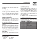
product. Table 1 shows the channel allocation.
Some of the 14 fixed channels are “DERIVED” read-
ings in that they are calculated from the other read-
ings. For example, power is calculated from both volt-
age and current. These are not real hardware chan-
nels, but they result in an analog reading that can be
treated as a “fixed channel” just like any other.
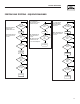
ANALOG MATHS
Each of the 23 channels is processed by a set of mea-
suring rules using constants that are set via GenLink.
Usually these constants can be changed by the cus-
tomer. In the following illustration, the measurement
is represented by M and the GenLink constants are
in italics. The measurement is processed in the fol-
lowing order and the result is then stored for cus-
tomer display or use.
M = M * Calibration Factor
This is used to calibrate out any reading inaccura-
cies where calibration factor is a number such that
1024 is equivalent to 1, so it’s really M * calibration
factor/ 1024. GenLink will hide this computation so
you can enter floating point numbers such as 1.1 or
0.987 etc.
THEN
M = M processed by function x:
General Information
H-100 Control Panel Technical Manual
CPU
Channel Derived
No. Channel Title Update Rate Value
7 User Configurable #1 (Usually Oil Temp) 3.84 ms No
8 User Configurable #2 (Usually Coolant Temp) 3.84 ms No
9 User Configurable #3 (Usually Oil Pressure) 3.84 ms No
10 User Configurable #4 (Usually Coolant Level) 3.84 ms No
11 User Configurable #5 (Usually Fuel level) 3.84 ms No
12 User Configurable #6 - Spare - 3.84 ms No
13 User Configurable #7 (Usually throttle position) 3.84 ms No
14 Special Oxygen sensor 3.84 ms No
15 Special Battery charge sensor 3.84 ms No
16 Battery Voltage/ PSU voltages 3.84 ms No
1 Generator Phase A RMS Current Phase A ZERO CROSSING No
2 Generator Phase B RMS Current Phase B ZERO CROSSING No
3 Generator Phase C RMS Current Phase C ZERO CROSSING No
- Generator average current Every Phase ZERO CROSSING Yes
4 Generator Phase A RMS Voltage Phase A ZERO CROSSING No
5 Generator Phase B RMS Voltage Phase B ZERO CROSSING No
6 Generator Phase C RMS Voltage Phase C ZERO CROSSING No
- Generator average voltage Every Phase ZERO CROSSING Yes
- Total Generator Power KW Every Phase ZERO CROSSING Yes
- Total Generator Power Factor Every Phase ZERO CROSSING Yes
- Generator Frequency Every Phase ZERO CROSSING Yes
- RPM #1 4 - 8 ms variable (geared) Yes
- Oxygen sensor zero crossings Every O2 ZERO CROSSING No
Table 1