Generator INSTALLATION GUIDELINES Air-Cooled Generators Distributed Load Center Transfer Switch OG 2697
This booklet and the accompanying video are designed to familiarize you with the installation process for your air-cooled generator. Neither this booklet nor the accompanying video replace or supersede any information contained in any of the written documents shipped with your equipment. This booklet should only be used in conjunction with the Owner’s Manual, Installation Guide and other technical documents shipped with your equipment.
This exhaust system must be installed properly, in strict compliance with applicable codes and standards. to isolate the electrical system from the utility distribution system when the generator is operating. Failure to isolate the electrical system by these means will result in damage to the generator and may also result in injury or death to utility workers due to backfeed of electric energy. Keep hands, feet, clothing, etc., away from drive belts, fans and other moving or hot parts.
NFPA 101, LIFE SAFETY CODE Grounding the Generator NFPA 110, STANDARD FOR EMERGENCY AND STANDBY POWER SYSTEMS A grounding lug is provided on the generator mounting base for the purpose of grounding the frame and the external electrically conductive parts of this equipment to an approved earth ground and/or grounding rods where required by the National Electrical Code. Grounding procedures must meet local regulations.
Do not open or mutilate the battery. Released electrolyte can be toxic and harmful to the skin and eyes. Servicing of batteries is to be performed or supervised by personnel knowledgeable of batteries and the required precautions. Keep unauthorized personnel away from batteries. The battery represents a risk of high short-circuit current. When working on the battery, always remove watches, rings or other metal objects, and only use tools that have insulated handles.
Before You Begin Carefully read and follow all of the procedures and safety precautions detailed in the installation guide. If you do not completely understand any portion of the installation manual, technical manual or other factory-supplied documents, contact an authorized dealer for assistance. Fully comply with all relevant NEC, NFPA and OSHA standards as well as all federal, state and local building and electric codes.
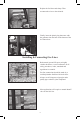
Make sure the lifting equipment you’ll be using has sufficient capacity to safely handle the weight of the generator. Use nylon lifting straps and connect them to the lifting eyes on each corner of the base frame to avoid damaging the enclosure. Set the generator onto the pad so that the gravel bed extends several inches beyond the generator on all sides. Make sure the generator is level within ½ inch. Some locations require the use of a poured concrete mounting pad.
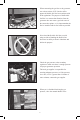
Check the engine oil, and if necessary, add enough of the recommended oil to bring the level up to the FULL mark on the dipstick. Be careful not to overfill the crankcase. Converting To LP Vapor The generator was configured for natural gas operation at the factory. Switching over to LP vapor is a simple procedure. On models with the V-Twin engine, simply flip the fuel selection switch from natural gas to LP. On models with a single-cylinder engine, start by making sure the battery is disconnected.
Replace the fuel hose and clamp. Then reconnect the wires to the solenoid. Finally, insert the plastic plug that came with the generator into the hole on the bottom of the air cleaner base. Installing & Connecting Gas Lines Both natural gas and LP vapor are highly volatile substances, so strict adherence to all safety procedures, codes, standards and regulations is essential. Gas line connections should be made by a certified plumber familiar with local codes.
When connecting the gas line to the generator, use a short section of UL Listed or AGAapproved flexible fuel line in accordance with local regulations. The purpose of the flexible fuel line is to ensure that vibration from the generator does not cause a gas leak at one of the connection points, so it’s important that the line be installed with as few bends as possible. Never bend the flexible fuel line to avoid using an elbow.
External Electrical Connections Drill a 1¾ inch hole and feed the conduit through the hole. Remove the knockout in the back of the connection box, feed the wires through the back of the box and secure the conduit with the lock nut. Seal the hole with silicone caulk. Don’t forget to caulk the hole inside the house as well. Mount the connection box so that it completely covers the hole in the wall. Connect all wires to the lugs in the connection box (black to black, red to red and white to white).
Installing The Automatic Transfer Switch Before beginning any installation, make sure power is shut OFF to the main distribution panel and carefully read the Installation Guide that came with your transfer switch. The distributed load center switch must be mounted close enough to the main distribution panel to accommodate the two-foot, pre-wired conduit. Make sure no water or corrosive substances can drip onto the transfer switch enclosure. Always inspect the switch for shipping damage.
When three-conductor wiring is used, two 120 volt circuits will often share the same neutral wire. To avoid overloading the neutral, you should either move BOTH of the circuits that share the neutral or don’t move either of them. When moving two circuits with a shared neutral, they should be connected to adjacent positions (one above the other) in the transfer switch. That will assure that the two hot wires are on separate phases and will maintain their relationship to neutral.
Install a 2-pole breaker in the distribution panel to protect the transfer switch. The required Amp rating of the breaker depends on which transfer switch you’re using, so refer to the Installation Guide before purchasing the breaker. Install the breaker in two adjacent empty slots (one above the other) in the main panel. When all emergency circuits have been moved to the transfer switch, close the main breaker to restore utility power and make sure utility voltage at the transfer switch is correct.
Locate the transfer handle and insert the metal end into the slot in the main contactor assembly. Pull the handle DOWN to move the main contacts to the standby power (generator) position. NEVER OPERATE THE TRANSFER SWITCH MANUALLY WHEN LOADS ARE CONNECTED. Put the generator’s mode switch in MANUAL to start the engine. Allow the engine to warm up, then switch the generator’s main breaker to the ON position. The generator is now supplying electricity to the transfer switch but is not carrying any load.
Use the transfer handle to move the main contacts in the transfer switch to the UP (utility) position. Switch the 2-pole breaker ON in the distribution panel. Now switch the generator’s main breaker ON and put the mode switch in AUTO. Shut OFF utility power and make sure the generator starts automatically. If everything worked properly, switch the main breaker to ON and make sure that power is automatically transferred back to the utility.
After the engine has completed its cool down cycle and shut down, shut OFF utility power again. When the generator is supplying power to the transfer switch, move the breakers in the switch to the ON position one at a time until the generator has accepted the entire emergency load. With the generator carrying the entire emergency load, re-check gas pressure to verify that it is at the same level it was before you started the generator. Switch the main breaker ON to restore utility power.
Shut OFF utility power again. The generator should start and the entire emergency load should transfer to the generator. Close the main breaker to restore utility power and allow the engine to cool down and shut itself OFF. Setting The Automatic Exercise Function With the mode switch in AUTO, press the EXERCISER switch. Hold it down for at least 10 seconds and release. The generator should start within a few seconds. The unit will run for about 12 minutes before shutting itself down automatically.
Notes 18
Every installation has its own unique set of circumstances and requirements. This booklet provides guidelines for basic installations only and is not intended to cover all applications. If you have any questions or concerns after carefully reading all documentation received with the equipment, contact your local dealer for assistance. Part# 0G2697 Printed in USA 08/06 ©2006 Generac Power Systems, Inc. All rights reserved.