Owner’s Manual 60 Hz Air-Cooled Generators 7.5 kW PowerPact™ WARNING Loss of life. This product is not intended to be used in a critical life support application. Failure to adhere to this warning could result in death or serious injury. (000209b) Register your Generac product at: WWW.GENERAC.COM 1-888-GENERAC (888-436-3722) Para español , visita: http://www.generac.com/service-support/product-support-lookup Pour le français, visiter : http://www.generac.
Use this page to record important information about your generator set. Serial: Record the information found on your unit data label on this page. The unit has a label plate affixed to the inside partition, above the battery access panel as shown in Figure 2-1. For directions on how to open the top lid and remove the front panel, see the Owner’s Manual.
Table of Contents Section 1: Safety Information Introduction ..........................................................1 Read This Manual Thoroughly ....................................1 Shutting Generator Down While Under Load Or During A Utility Outage ..................................... 15 Auxiliary Shutdown Switch .............................. 16 How to Obtain Service .................................................1 Safety Rules .........................................................
Table of Contents This page intentionally left blank.
Safety Information Section 1: Safety Information Introduction Thank you for purchasing this compact, high performance, air-cooled, engine-driven generator. It is designed to automatically supply electrical power to operate critical loads during a utility power failure. This unit is factory installed in an all-weather, metal enclosure intended exclusively for outdoor installation. This generator will operate using either vapor withdrawn liquid propane (LP) or natural gas (NG).
Safety Information Safety Rules WARNING Study these SAFETY RULES carefully before installing, operating or servicing this equipment. Become familiar with this Owner’s Manual and with the unit. The generator can operate safely, efficiently and reliably only if it is properly installed, operated and maintained. Many accidents are caused by failing to follow simple and fundamental rules or precautions. Accidental Start-up.
Safety Information WARNING Risk of injury. Do not operate or service this machine if not fully alert. Fatigue can impair the ability to service this equipment and could result in death or serious injury. (000215) WARNING Injury and equipment damage. Do not use generator as a step. Doing so could result in falling, damaged parts, unsafe equipment operation, and could result in death or serious injury. (000216) Inspect the generator regularly.
Safety Information Fire Hazards Explosion Hazards DANGER WARNING Fire hazard. Do not obstruct cooling and ventilating airflow around the generator. Inadequate ventilation could result in fire hazard, possible equipment damage, death or serious injury. (000217) Explosion and fire. Fuel and vapors are extremely flammable and explosive. No leakage of fuel is permitted. Keep fire and spark away. Failure to do so will result in death or serious injury. (000192) DANGER WARNING Fire and explosion.
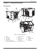
General Information Section 2: General Information The Generator A B H J K L M C D G N P O E F R Q 005568 Figure 2-1. Features and Components A. Top Lid G. Fuel Connection Hole N. Air Box B. Controller Lid H. Data Label O. Spark Plug C. Control Panel J. Battery Access Panel P. Exhaust Enclosure D. Circuit Breaker K. Oil Drain Hose Q. Alternator E. Customer Connection Box L. Oil Fill / Dipstick R. Starter Motor F. Auxiliary Engine Shutdown Switch M.
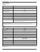
General Information Specifications Generator Model Rated Voltage 7.5 kW 240 Rated Maximum Load Current (Amps) at Rated Volts (LP)* Main Line Circuit Breaker (Generator Disconnect) Phase 31.25 35 Amp 1 Rated AC Frequency 60 Hz Battery Requirement Group U1, 12 Volts and 300 CCA Minimum (see Replacement Parts) Enclosure Galvanneal Steel Unit Weight 280 lb (127.
General Information Data Decals Two decals on the generator provide information about the unit itself and the required fuel inlet pressure for proper operation. Model Data Decal 20xx/xx/xx Includes important information about the unit including: • model number • serial number • production date • voltage • frequency • amps • country of origin • rated ambient temperature. The model data decal also displays certification symbols by Underwriter’s Laboratory (UL) and the Southwest Research Institute (SwRI).
General Information Protection Systems The generator may have to run for long periods of time with no operator present to monitor the engine/generator conditions. Therefore, the generator is equipped with a number of systems to automatically shut down the unit to protect it against potentially damaging conditions.
General Information Replacement Parts Description 7.5 kW U1 Exide Battery 0J5584 Spark Plug 0L3059 Air Filter 0E9371A Control Panel Fuse (7.5 Amp) 0D7178T Transfer Switch Fuses Refer to Transfer Switch Owner’s Manual for part number Accessories Performance enhancing accessories are available for air-cooled generators. Accessory Description Cold Weather Kit G006808-1 Recommended in areas where temperatures fall below 32 ºF (0 ºC).
General Information This page intentionally left blank. 10 Owner’s Manual for 7.
Operation Section 3: Operation Site Prep Verification Controller Lid It is important that the generator is installed in such a way that the airflow into and out of the generator is not impeded. Verify that all shrubs or tall grasses have been removed within 3 ft (0.91 m) of the intake and discharge louvers on the sides of the enclosure. It is also important that the generator is not subject to water intrusion.
Operation Control Panel A The Control Panel is located under the Controller Lid. Open the Controller Lid to access the control panel (B in Figure 3-2). B The Auto/Off/Manual Interface located on the Control Panel has the following features (see Figure 3-3): • Alarm LEDs (A) • Warning LEDs (B) • Operation Mode Buttons and LEDs (C) C 001052 Figure 3-3.
Operation Alarm Response Procedures The generator is protected by a series of sensors that will detect an Alarm/Warning condition and alert the owner/ operator of the condition via the Control Panel display. When certain alarm conditions are detected, the generator will shut down. NOTE: Unless properly trained to clear and correct Warning and Alarm conditions, contact the nearest IASD or Trained Technician.
Operation 5. To crank and start the engine, press the control panel MANUAL button. A 6. Allow the engine to stabilize and warm up for a few minutes. 7. Set the main line circuit breaker (Generator Disconnect) to ON or CLOSED. The standby power source now powers the loads. B 000947 Figure 3-4. Manual Transfer Switch Operation IMPORTANT NOTE: Actual switch operation may vary. Follow directions in the appropriate transfer switch manual. MANUAL • Will not transfer to generator if utility is present.
Operation Automatic Sequence of Operation Utility Failure With the generator set to AUTO, when utility fails (below 65% of nominal) a five second line interrupt delay time is started. If utility is still gone when the timer expires, the engine will crank and start. Once started, a six second engine warm-up timer will be initiated (or a 30 second warm-up timer; refer to Cold Smart Start). When the warmup time expires, the control panel will transfer the load to the generator.
Operation Auxiliary Shutdown Switch All generators are provided with an external means to shut down the generator that complies with the 2017 NEC code requirement. The primary generator shutdown sequence is described in the previous topic. See Figure 3-5. An auxiliary shutdown switch is located on the exterior of the generator back panel. This switch shuts down the generator and disables restarts. 005570 005570 Figure 3-5.
Maintenance Section 4: Maintenance Maintenance Regular maintenance will improve performance and extend engine/equipment life. Generac Power Systems, Inc. recommends that all maintenance work be performed by an Independent Authorized Service Dealer (IASD). Regular maintenance, replacement or repair of the emissions control devices and systems may be performed by any repair shop or person of the owner’s choosing.
Maintenance Service Schedule Table 4-1.
Maintenance Maintenance Log Battery inspection and charge check Dates Performed: Oil, oil filter, air filter and spark plug replacement Dates Performed: Valve Adjustment Dates Performed: Notes: Owner’s Manual for 7.
Maintenance Checking Engine Oil Level WARNING Risk of burns. Allow engine to cool before draining oil or coolant. Failure to do so could result in death or serious injury. (000139) 9. If necessary, remove the dipstick/fill cap and add oil to the engine until the level reaches the FULL mark and reinsert the dipstick and fill cap. 10. If the generator was running during a utility outage, turn the main circuit breaker to the ON position. 11. Install the 7.5 Amp fuse in the generator control panel. 12.
Maintenance Changing the Oil 13. Insert dipstick/fill cap and hand tighten. 14. Press the Control Panel AUTO button. 15. Dispose of the used oil and filter at a proper collection center. WARNING Skin irritation. Avoid prolonged or repeated contact with used motor oil. Used motor oil has been shown to cause skin cancer in laboratory animals. Thoroughly wash exposed areas with soap and water. (000210) 1.
Maintenance Spark Plug B Check the spark plug gap and replace the spark plug as necessary: 1. With the generator shut down, remove the top lid. E 2. Clean the area around the base of the spark plug to keep dirt and debris out of the engine. C D A 3. Gently pull the spark plug boot off of the spark plug. 4. Remove the spark plug and check the condition. Install a new plug if the old plug is worn or if reuse is questionable. 5.
Maintenance 7. Turn the pivot ball stud (B) while checking clearance between the rocker arm (C) and the valve stem (D) with a feeler gauge (E). Correct clearance is 0.002– 0.004 in. (0.05–0.1 mm). NOTE: Hold the rocker arm jam nut in place as the pivot ball stud is turned. WARNING Electrical shock. Disconnect battery ground terminal before working on battery or battery wires. Failure to do so could result in death or serious injury. (000164) 8.
Maintenance Always recycle batteries in accordance with local laws and regulations. Contact your local solid waste collection site or recycling facility to obtain information on local recycling processes. For more information on battery recycling, visit the Battery Council International website at: http:// batterycouncil.org/. Attention After Submersion If the generator has been submerged in water, it MUST NOT be started and operated.
Troubleshooting Section 5: Troubleshooting System Diagnosis Problem Engine will not crank. Cause 1. Fuse blown. Correction 1. Correct short circuit condition by replacing 7.5 Amp fuse in generator control panel. 2. Loose, corroded or defective battery cables. 2. Tighten, clean or replace as necessary.* 3. Defective starter contact. 3. *See #2. 4. Defective starter motor. 4. *See #2. 5. Dead battery. 5. Charge or replace battery. 6. Auxiliary shutdown switch is OPEN (O). 6.
Troubleshooting This page intentionally left blank. 26 Owner’s Manual for 7.
Quick Reference Guide Section 6: Quick Reference Guide System Diagnosis To clear an active alarm, press the OFF button twice and then press AUTO. If the alarm reoccurs, contact an Independent Authorized Service Dealer (IASD). Table 6-1. System Diagnosis Active Alarm Problem NONE Unit running in AUTO but Check MLCB. no power in house. Check MLCB. If it is in the ON position, contact an IASD. HIGH TEMPERATURE Unit shuts down during operation. Check the Controller for alarms.
Quick Reference Guide Table 6-1. System Diagnosis (Continued) Active Alarm Problem Things to Check Solution 1 YEAR / 100 HOUR MAINTENANCE DUE Control panel indicates scheduled maintenance due.LED illuminates. None Perform scheduled maintenance. Clear Maintenance Due light. NONE Utility present. Generator Check utility sense running. Active mode lines / utility LED (AUTO/MANUAL/ disconnect. OFF) is flashing. 28 Contact IASD. Close utility disconnect. Owner’s Manual for 7.
Quick Reference Guide This page intentionally left blank. Owner’s Manual for 7.
Quick Reference Guide This page intentionally left blank. 30 Owner’s Manual for 7.
Part No. 10000021790 Rev. A 02/21/18 ©2018 Generac Power Systems, Inc. All rights reserved Specifications are subject to change without notice. No reproduction allowed in any form without prior written consent from Generac Power Systems, Inc. Generac Power Systems, Inc. S45 W29290 Hwy. 59 Waukesha, WI 53189 1-888-GENERAC (1-888-436-3722) www.generac.