Owner’s Manual Field and Brush Mower 005811 MODEL NUMBER: _________________________ SERIAL NUMBER: _________________________ DATE PURCHASED:________________________ Register your Generac product at: WWW.GENERAC.
WARNING CANCER AND REPRODUCTIVE HARM www.P65Warnings.ca.gov.
Table of Contents Section 1: Safety Rules & General Information If Mower Gets Stuck ...................................................13 Introduction ..................................................................1 Read This Manual Thoroughly ....................................1 Deck Pivot Bolt Adjustment for Aggressive Mowing Conditions ....................................................13 Mowing on Slopes .....................................................13 Safety Rules .....................
This page intentionally left blank.
Safety Rules & General Information Section 1: Safety Rules & General Information Introduction Thank you for purchasing a Generac Power Systems Inc. product. This unit has been designed to provide high performance, efficient operation, and years of use when maintained properly. The information in this manual is accurate based on products produced at the time of publication. The manufacturer reserves the right to make technical updates, corrections, and product revisions at any time without notice.
Safety Rules & General Information General Hazards WARNING WARNING Accidental Start-up. Disconnect the negative battery cable, then the positive battery cable when working on unit. Failure to do so could result in death or serious injury. (000130) Moving Parts. Keep clothing, hair, and appendages away from moving parts. Failure to do so could result in death or serious injury. (000111) WARNING WARNING Personal injury. Keep out of reach of children.
Safety Rules & General Information Exhaust and Fuel Hazards Fire Hazards DANGER WARNING Asphyxiation. Running engines produce carbon monoxide, a colorless, odorless, poisonous gas. Carbon monoxide, if not avoided, will result in death or serious injury. (000103) DANGER Risk of Fire. Verify machine has properly cooled before installing cover and storing machine. Hot surfaces could result in fire. (000109) WARNING Explosion and Fire. Fuel and vapors are extremely flammable and explosive.
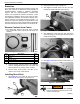
Safety Rules & General Information Safety and Operating Decals This unit features numerous safety and operating decals. These decals provide important operating instructions and warn of dangers and hazards. Replace damaged or missing safety and operating decals immediately.
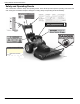
General Information and Setup Section 2: General Information and Setup I A Brush Blade (under deck) M Key Switch B Brush Bar N Operator Presence Control C Brush Deck O Brake/Steering Lever D Belt Guard P Fuel Filter E Oil Fill/Dipstick Q Muffler F Engine (18.67 hp shown) R Oil Filter G Fuel Tank S Oil Drain H Fuel Fill I Wheel Speed Lever J Traction Drive Lever J L N M K H O G F E P K Throttle Lever Q L PTO Knob R D S B C 005828 A Figure 2-1.
General Information and Setup Emissions 2. Place brush deck in front of power unit. The United States Environmental Protection Agency (US EPA) (and California Air Resources Board (CARB), for engines/equipment certified to California standards) requires that this engine/equipment complies with exhaust and evaporative emissions standards. Locate the emissions compliance decal on the engine to determine applicable standards. For emissions warranty information, reference the included emissions warranty.
General Information and Setup 6. See Figure 2-7. Place belt onto deck pulley. Gradually turn belt pulley to assist belt into pulley groove. 3. See Figure 2-10. Rotate blade pulley to roll belt off blade pulley (C). C 005833 005833 Figure 2-10. Removing Belt from Blade Figure 2-7. Install Belt on Spindle Pulley 7. See Figure 2-8. Install and secure belt guard with provided hardware. 4. See Figure 2-11. Push the belt toward the power unit, and the belt will fall off clutch pulley (D).
General Information and Setup Maintenance Meter Installation Adding Oil 1. Gently pry black panel insert from control panel 2. Insert panel adapter from kit into open hole in control panel. Verify adapter engages panel completely. 3. See Figure 2-13. Insert meter (A) firmly into panel adapter (B) until it snaps into place. The meter flange should be flat against the adapter face. CAUTION Engine damage. Verify proper type and quantity of engine oil prior to starting engine.
General Information and Setup 6. If oil level is low, add a few ounces of oil at a time, rechecking the dipstick until the oil reaches the “MAX” mark. Do not overfill. 7. Fully tighten the cap, and wipe i[ any spilled oil. Adding Fuel DANGER Explosion and Fire. Fuel and vapors are extremely flammable and explosive. Add fuel in a well ventilated area. Keep fire and spark away. Failure to do so will result in death or serious injury. (000105) Checking Tire Pressure WARNING Loss of control.
General Information and Setup Handlebar Height Adjustment All units are shipped with the handlebar set to the highest position. To adjust the handlebar to lower positions: 1. See Figure 2-20. Remove rear handlebar bolt (A) with a 9/16 in wrench from both sides of the unit. 4. Hold the square portion of carriage bolt (A) using a 1/2 in wrench. 5. Tighten locknut (B). Steering Brake Burnishing Brake pads and rotors must be burnished during first use. To burnish the steering brake system: A 1.
Operation Section 3: Operation WARNING Consult Manual. Read and understand manual completely before using product. Failure to completely understand manual and product could result in death or serious injury. (000100a) WARNING Hot Surfaces. When operating machine, do not touch hot surfaces. Keep machine away from combustibles during use. Hot surfaces could result in severe burns or fire. (000108) Before Starting Engine IMPORTANT NOTE: Oil must be added before starting the engine for the first time.
Operation 3. Move throttle lever to CHOKE or FAST if the engine is already warm. 4. Rotate key to the START position until the engine starts, then release. The key will return to the RUN position. 5. Set throttle lever to the FAST position. Engaging Mower Blade WARNING Personal injury, equipment damage. Always disengage mower blade before shifting into reverse. Failure to do so could result in serious injury or equipment damage.
Operation Steering with Brake Assist Mowing on Slopes 1. See Figure 3-7. Set wheel speed lever (A) to gear best suited for the application. See Engaging Wheel Drive. WARNING Personal injury, equipment damage. Always mow across the face of a slope. Never mow slopes greater than 20 degrees. Failure to do so could result in a slip and fall, resulting in loss of control of the equipment and could result in death or (000404) serious injury. 2. Engage traction drive lever (B) to drive the machine.
Operation This page intentionally left blank.
Maintenance and Troubleshooting Section 4: Maintenance and Troubleshooting Maintenance Regular maintenance will improve performance and extend engine/equipment life. Regular maintenance, replacement, or repair of the emissions control devices and systems may be performed by any repair shop or person of the owner’s choosing. To obtain emissions control warranty service free of charge, contact Generac Customer Service at 1-888436-3722 (1-888-GENERAC), or www.generac.com. See the emissions warranty.
Maintenance and Troubleshooting Operating the Maintenance Meter See Figure 4-1. The maintenance meter monitors the accumulated running time, time until the engine oil needs to be changed, and time until lubrication is recommended. Pressing function button (A) cycles through meter functions. Changing Engine Oil and Filter CAUTION Engine damage. Verify proper type and quantity of engine oil prior to starting engine. Failure to do so could result in engine damage. (000135) WARNING Skin irritation.
Maintenance and Troubleshooting Servicing Spark Plug Adjusting Traction Drive Cable To service spark plug: NOTE: When properly adjusted, the traction drive lever increases cable tension when the lever is parallel to the handlebar grip. 1. Clean area around spark plug. 2. Remove and inspect spark plug. 3. See Figure 4-4. Inspect electrode gap with wire feel gauge and reset spark plug gap to .024-.032 in (0.6-0.8 mm). 1. See Figure 4-6. Locate traction drive cable (A) along right handlebar.
Maintenance and Troubleshooting Replacing Drive Belt 7. Remove clutch from engine shaft. 1. See Figure 4-8. Remove brush deck (see Removing Brush Deck) and tip the machine back on its handlebars to access clutch connector (A). 8. See Figure 4-11. Remove belt guide retaining nuts (F) with a 1/2” socket. G H F A 005833 005855 Figure 4-11. Clutch Removal Figure 4-8. Clutch Connector Location 2. See Figure 4-9. Disconnect clutch connector (B) by lifting the locking tab and separating the halves. 9.
Maintenance and Troubleshooting Replacing Mower Blade 3. See Figure 4-15. Block blade with a piece of wood to prevent it from rotating and remove locknut (C) with a 15/16” wrench. WARNING Personal injury. Mower blades are extremely sharp. Use appropriate personal protective equipment when handling and servicing blades, or use blade protection. Failure to do so could result in death or serious injury.
Maintenance and Troubleshooting Adjusting Brake Pads Battery Care The brake pads may require adjustment after pad wear. 1. Remove the wheel from the side being worked on. 2. See Figure 4-17. Locate pad adjustment screw (D) on the outboard side of the caliper. WARNING Explosion. Batteries emit explosive gases while charging. Keep fire and spark away. Wear protective gear when working with batteries. Failure to do so could result in death or serious injury. (000137a) C WARNING D E 005863 Figure 4-17.
Maintenance and Troubleshooting • Do not charge a fully charged battery. Heat from the trickle charger could damage the battery. The battery will read 12–13.2 volts when fully charged. • Do not crank the engine when battery charge is low. • Before charging the battery, observe its external appearance and keep it clean and dry. Never charge or use a battery that shows cracks, changes shape, leaks, or is otherwise damaged. Charging the Battery If the battery loses charge, recharge with a trickle charger.
Maintenance and Troubleshooting Symptom Possible Cause Inspect oil level and adjust as needed. Verify machine is not on a steep incline. Engine smokes Air filter may be dirty. Replace as necessary. Inspect cooling fins. Clean if necessary. Contact Generac Customer Service at 1-888-436-3722, or www.generac.com. Traction drive does not engage Inspect drive belt. Replace if broken. Repair if out of adjustment.
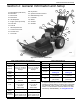
Part No. 10000024569 Rev. A 05/01/18 ©2018 Generac Power Systems, Inc. All rights reserved Specifications are subject to change without notice. No reproduction allowed in any form without prior written consent from Generac Power Systems, Inc. Generac Power Systems, Inc. S45 W29290 Hwy. 59 Waukesha, WI 53189 1-888-GENERAC (1-888-436-3722) www.generac.