OEM LTE PCIe Mini Module Integration OEM PCI Express Mini Module Integration Guide V01.
OEM LTE PCIe Mini Module Integration Contents 1 2 3 General ................................................................................................................ 3 1.1 Approvals and Dates ............................................................................................................... 3 1.2 Change Record ....................................................................................................................... 3 1.3 Acronyms .....................................
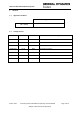
OEM LTE PCIe Mini Module Integration 1 1.1 General Approvals and Dates Approval Date W. J. Jones 1.2 Change Record Date Version Author 21/06/2012 01.00 PFW New Document. 14/08/2012 01.01 PFW Updated with LTE. 21/08/2012 01.02 PFW Updated with LTE Band 4, Band 14 removed. 03/09/2012 01.03 PFW Technical Corrections 21/03/2014 01.
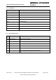
OEM LTE PCIe Mini Module Integration 1.3 Acronyms Term Definition MPE Maximum Permissible Exposure OEM Original Equipment Manufacturer PCIe PCI Express PCI SIG PCI Special Interest Group PEM PCI Express Mini SIM Subscriber Identity Module LTE Long Term Evolution USB Universal Serial Bus 1.
OEM LTE PCIe Mini Module Integration 2 Introduction This document describes the method of integrating the General Dynamics Broadband PCI Express Mini module into an OEM product. 2.1 Scope of Document This document applies to the General Dynamics Broadband PCI Express Mini module only. 2.
OEM LTE PCIe Mini Module Integration 3 Module Connections 3.1 PCI Express Mini Interface (J1) The General Dynamics Broadband PCI Express Mini module is provided with a 52 pin edge connector for connection to the external application. This connection supports the following interface types and these are described below. The pinout is shown in Annex 1. 3.1.1 Universal Serial Bus The PCI Express edge connector provides a USB 2.0 interface, this interface supports low speed (1.
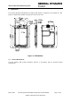
OEM LTE PCIe Mini Module Integration 4 Mechanical The General Dynamics Broadband PCI Express Mini module is designed to be installed in a PCI Express compliant slot capable of holding an F1 full size mini card. Figure 2: PEM Module 4.1 Thermal Management The PCI Express Mini module integration shall be in accordance with the PCISIG thermal requirements.
OEM LTE PCIe Mini Module Integration 5 Regulatory Information 5.1 Compliance with FCC Rules and Regulations The General Dynamics Broadband PCI Express Mini module is certified against FCC Part 27 for operation in the 699-716MHz (Band 12) and 1710-1755MHz (Band4) frequency allocations and FCC Part 90 for operation in the 788-798MHz (Band 14) frequency allocation.
OEM LTE PCIe Mini Module Integration 5.2 Exposure to Radio Frequency Signals To comply with the FCC RF exposure rules, the UE PCI Express Mini module has been evaluated against the Maximum Permissible Exposure (MPE) limits defined in Section 1.1310 of the FCC rules for the uncontrolled environment. During normal operation, all persons should maintain a distance of at least 20cm from the antenna to ensure compliance with the MPE limits.
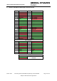
OEM LTE PCIe Mini Module Integration 6 Annex 1: PCI Express Mini Edge Connector Pinout Pin Name Pin Name 51 Reserved 52 +3.3Vaux 49 Reserved 50 GND 47 Reserved 48 +1.5V 45 Reserved 46 LED_WPAN# 43 GND 44 LED_WLAN# 41 +3.3Vaux 42 LED_WWAN# 39 +3.3Vaux 40 GND 37 GND 38 USB_D+ 35 GND 36 USB_D- 33 PETp0 34 GND 31 PETn0 32 SMB_DATA 29 GND 30 SMB_CLK 27 GND 28 +1.5V 25 PERp0 26 GND 23 PERn0 24 +3.