
Use and Care Manual


15
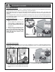
2. To adjust the left jaw, loosen bolts A and B using a
20 mm wrench.
3. Position the jaw to the desired angle, or squared to
the blade, and then tighten bolts A and B.
4. Repeat the previous steps with the right jaw using
the bolts C and D.
Note: Use the vise handwheel to open or close the
vise.
MAKE SURE THE MACHINE HAS BEEN TURNED OFF AND UNPLUGGED FROM THE POWER SOURCE BEFORE PERFORM-
ING ANY MAINTENANCE OR ADJUSTMENTS.
SQUARING THE VISE TO THE BLADE/USING THE VISE
(CONTINUED)
A
B
C
A
D
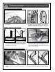
1. Loosen lock knobs E & F and push the two blade
guards G & H in the direction of the arrows. Shut off
the hydraulic downfeed control, and then lift the
arm into the vertical position.
2. Loosen nut I using a 14 mm opend wrench.
The guide bearings K keep the blade from moving from side to side during the cutting and must be adjusted
close to the blade (but not touching the blade) in order to ensure accurate cuts. The space between each guide
bearing and the blade must not exceed 0.001”. If less space is left, the blade will get stuck or jammed between the
bearings. Too much friction will cause blade to overheat and break.
Note: Before adjusting the blade guides, make sure the blade is tensioned and tracking properly. Re-adjust
the blade guides after each blade tension or tracking adjustment.
ADJUSTING THE BLADE GUIDES
3. Turn the eccentric shaft J with pliers until the blade
and bearing are about 0.001” apart as shown K.
4. To lock the bearing position, retighten nut I while
holding shaft J with pliers. Repeat steps 2 to 4 for the
other bearing, and then for the second assembly
located on the other side of the saw arm.
5. Make a test cut and re-adjust the blade guides if
needed.
0,001"
0,001"
K
J
I
E
G
F
H
LEFT SIDE
RIGHT SIDE