
Datasheet

ECONISTOR
(8E16 & 8E24)
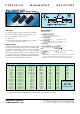
ORDERING PROCEDURE EXAMPLE:
8 E 1 6 A 10 K
lll
Style and general Tolerance: R value in Ohms
specifications X = 0.005% A = 0.01% D = 0.1%
Matched pairs and ratio matched resistors are available against specific enquiries.
3
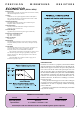
CONSTRUCTION
Econistors are wound on a proprietary multi-section bobbin
with the termination wires moulded deep into the body of the
bobbin. Each copper to resistance wire join is thus positioned
near to the centre of the resistor and spaced apart from each
other by only 2mm. This is an important factor in minimising
the effect of thermal EMFs (see separate note on thermal EMFs).
This method of construction also effectively isolates the fine
resistance wire mechanically from the termination wires. To
minimise inductance, the direction of winding is reversed at
the half turns point.
During the manufacturing process each resistor undergoes
an ageing process for a minimum of one week in a temperature
controlled oven in order to completely stabilise the winding
prior to calibration.
Econistors are encapsulated in a moulded epoxy shell which
fully seals the winding.
Resistance Wire
Highest quality copper alloy wire drawn from melts of known resistivity
and controlled temperature co-efficient.
Accuracy
Calibration is as 25°C against equipment traceable to NBS (United
States). During calibration, the electrical connection is made – 10mm
along the lead-out wires from the body.
~
Operating Temperature
The maximum operating temperature due to ambient and power
dissipation within the resistor is 160°C.
Solvent Resistance
The body material and identification marking is resistant to all
commonly used PC board solvents.
Lead Pull Strength
2kg (limited only by inherent strength of copper lead material).
Resistance of Termination Leads
Type 8E16 = 0.52m Ohms/cm
Type 8E24 = 0.33m Ohms/cm
Voltage Co-efficient
Essentially zero
Manufacturing
The highest quality materials are used; all processing is performed in
temperature/humidity controlled “clean rooms”, each step is carefully
monitored.
Thermal EMFS
The temperature difference between the two copper to resistance wire
joins is the critical factor. If the two junctions are at the same
temperature, then the effect of thermal EMFs is minimised.
The construction of Econistors is such that the two junctions are not
more than 2mm apart, thus reducing any possibility of temperature
difference almost to zero. This largely negates the effect of thermal
EMFs in Econistors.
The thermal EMF of the resistance material to copper join for
Econistors is typically <0.4µV/°C.
PRECISION WIREWOUND RESISTORS