
Installation Guide

Page 1/2
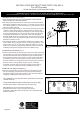
ASSEMBLING THE FIXTURE (Fig.1)
Fig.1
C
US
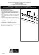
Fig.2
FIXTURE
WIRES
BLACKOR
SMOOTH
FIXTURE
WIRES
WHITEOR
RIBBED
FIXTURE
WIRES
GREENOR
BARE
COPPER
(GROUND)
HOUSE
WIRES
BLACK
(HOT)
HOUSE
WIRES
WHITE
(NEUTRAL)
HOUSE
WIRES
GREENOR
BARECOPPER
(GROUND)
1
Shut off power at the fuse box or circuit breaker. remove the old
fixture including the mounting hardware.
CONNECTING THE WIRES (Fig. 2)
FINISHING THE INSTALLATION (Fig.1)
Your installation is now complete. Return power to the junction box
and test the fixture.
CAUTION/ATTENTION: When handling the fixture,do not apply
pressure to the LEDs. Hold the fixture by the frame only.
WARNING! SHUT POWER OFF AT FUSE OR CIRCUIT BREAKER
AVERTISSEMENT!COUPER LE COURANT AU NIVEAU DES FUSIBLES OU DO DISJONCTEU
READ AND SAVE THESE INSTRUCTIONS
For LED Pendant
INSTALLATION INSTRUCTIONS FORP1154-655-L
IMPORTANT: Fixture should be installed by a
qualified electrician to ensure proper wiring and
installation.Dimmable with ELV and/or LED compatible wall
dimmer switches.
G
F
S
A
B
C
D
U
T
V
W
E
2 Carefully remove the fixture from the carton and check that all
parts areincluded as show in Figure 1. Unscrew ( G ) to remove
the mounting plate ( A ) from the canopy ( F),unscrew hex nut to
take the square plate off.
3 Position mounting plate(A) on the ceiling ,and mark the location
of the dry wall anchors(W).Pre-drill the holes for the dry wall
anchors ,Insert the dry wall anchors(W) into the ceiling ,Attach
the mounting plate (A) to the junction box using the mounting
screws(B,size 8#-32N 1/2'’).The side of the mounting plate
marked “GND” must face out.Place the wood screw (T) through
the slot hole into the dry wall anchor(W) to secure the mounting
plate(A) as shown in Fig. 1.
4 The support cable(E) is provided to support the weight of the
fixture while wiring .Align the fixture to mounting plate(A) and
attach quick link (U) on the end of support cable (E) into the
hookholeonthemountingplate(A).Carefullyallowthesupport
cable(E)tosupporttheweightofthefixturewhilewiring.
5 Pass the black/white and bare copper wires from the hole of the
square plate (V), and let the square plate rest on the canopy (F).
Connect the electrical wire as shown in figure 2,making sure
that all wire connectors are secured. If your junction box has a
ground wire (green or bare copper),connect the ground wire
from the fixture to it. Otherwise connect fixture ground wire (C)
directly to the mounting plate using the green screw (D)
provided. Tuck the wire connections neatly into the ceiling
junction box as you hold the canopy towards the ceiling.
6 Rise the square plate (V) to the studs to fix with the hex nuts.
) Fix the canopy(F) into the mounting plate (A with finial(G).
Adjust the ength of the cable to pull or push l until the desired
length by pushing down the spring nut (S)