ENGLISH - DATA MANAGER DATA ACQUISITION SOFTWARE USER GUIDE
ENGLISH DATA MANAGER – SOFTWARE Release 0.0.0 2013 GET by Athena Evolution. All rights reserved. The contents of this document, or any part of it, may not be reproduced, transferred, distributed or memorised in any form whatsoever without the written permission of GET by Athena Evolution s.r.l. GET reserves the right to modify the content of this manual without prior notice. DATA MANAGER - GET DATA ACQUISITION SOFTWARE rev.
1 BEFORE STARTING............................................................................................................................... 5 1.1 INSTALLING SOFTWARE ...................................................................................................................... 5 1.1.1 System Requirements........................................................................................................................... 5 1.1.2 Installing software on Microsoft Windows© .....................
ENGLISH 3.2.18.1 Creating a new report .................................................................................................................... 49 3.2.18.2 Updating an existing report ............................................................................................................ 50 3.2.18.3 Best split times and ideal lap ......................................................................................................... 50 3.2.18.4 Saving and loading a report .................
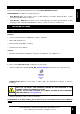
1 BEFORE STARTING DATA MANAGER is available in two different license: • Data Manager free: the freeware version of Data Manager (it includes Download Data , Config Datalogger and Mx2 analysis software) • Data Manager – WINTAX: the payment version of Data Manager (it includes Download Data , Config Datalogger, Mx2, Magneti Marelli WINTAX 4 analysis software and license hardware key) 1.1 INSTALLING SOFTWARE 1.1.
2 THE SOFTWARE COMPONENTS ENGLISH The components of DATA MANAGER are: • Data Manager software: allows the data download and configuration of GET data logger • MX2 analysis software: allows the sessions analysis recorded by GET data loggers • WinTAX4 analysis software : allows the sessions analysis recorded by GET data loggers (only for payment license) The icons will be displayed after the end of software installation (see previous chapter). 6 DATA MANAGER - GET DATA ACQUISITION SOFTWARE rev.
3.1 DATA MANAGER: THE ANALYSIS SOFTWARE ENGLISH 3 WinTAX4 analysis software All of operative procedures and features of WinTAX4 software are available on corresponding help file (find it on software Help menù). THE USB KEY (HARDWARE LICENSE KEY) HAVE TO BE INSERTED BEFORE RUNNING THE ANALYSIS SOFTWARE Click on the software icon to run WinTAX4: DATA MANAGER - GET DATA ACQUISITION SOFTWARE rev.
3.2 MX2 analysis software ENGLISH MX2 is the software which allows the user to analyse the data collected by the GET devices. The first time the program is started up, a demonstration project is automatically loaded. This is useful in order to become familiar with the main functions available. 3.2.
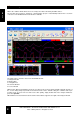
The analysis window is the main area of the MX2 software. This window shows the values of the acquired channels in a graph format. FINISH LINE LAP BAR Y AXIS X AXIS ASSE X SPLIT TIME LINEAR MAP It is possible to add more channels to be displayed on the main window, or to create tabs onto which to distribute all the channels to be analysed in the most suitable way.
ENGLISH TAB 2: SUSPENSION CHANNELS TAB 3: SPEED AND ACCELERATION CHANNELS If an individual lap is being analysed, each channel is represented with a different colour graph. If this is not the case, and several laps are being analysed at the same time, the graphs are represented with the colours of the corresponding laps. The analysis window is also composed of the following elements: • Y axis: this shows the scale and the name of each channel displayed, using the same colour as the graph.
The main toolbar is situated at the top of the program window and allows the user quick access to the most commonly used software functions.
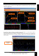
3.2.5 Overview window (overview bar) ENGLISH The default position of the overview window is in the bottom left-hand corner of the window. This area provides an overview of the session used, listing the available laps and displaying the graphs of the channels selected for the whole session.
ANALYSIS CURSOR REFERENCE CURSOR If the finish line and split points have been added to the track, they will be visible in the Track Bar as grey lines which divide the track. FINISH LINE SPLIT POINTS DATA MANAGER - GET DATA ACQUISITION SOFTWARE rev. 01 2013 - GET by Athena Evolution - All rights reserved 13 ENGLISH If MX2 is in measurement mode, a circle-shaped indicator with the colour of the lap selected will appear automatically.
3.2.7 Creating and managing projects ENGLISH The MX2 software uses project files to manage the set of data and settings used. The session loaded, the channels used and the display and track settings are specified in these files. Through the project files, it is possible to save the program mode in order to recall it later on. This allows the user to ensure that the working environment used at the moment when the project was saved is always available.
Once a new project has been created or an existing project opened, it is possible to add laps by selecting the sessions to be used. In order to select a session from those which are available, it is necessary to open the browser bar from the left-hand navigation bar. If the window is opened in the minimised format, expand it by clicking on the arrow positioned in the top right-hand corner of the window itself.
ENGLISH When a session is selected, the laps available are listed in the control on the right, while in the bottom lefthand corner, a preview of the course to which the session refers is displayed. In the list of the available laps, the lap number, corresponding time and any notes are present for each heading. The fastest lap of the session is shown in red.
ENGLISH For each heading, the list containing all the laps added to the project summarises the information regarding the lap itself and the corresponding session, in order to identify all the laps listed with precision and speed. LAPS ADDED TO THE PROJECT For each lap added to the project, a tab is also created in the overview window. By clicking on each of these tabs, the corresponding lap will be loaded and the program interface will be updated with the corresponding data.
3.2.9 Displaying the channels ENGLISH After adding laps to the project, it is possible to select the channels to be displayed in the analysis window. In order to do this, it is necessary to open the channels window, by clicking on the corresponding symbol on the left-hand navigation bar. The first time the program is run, the window is opened in the minimised format, and therefore it is necessary to expand it by clicking on the arrow positioned in the top right-hand corner of the window itself.
The bottom of the window, on the other hand, offers a list of available channels for the session selected. VISIBLE FEATURE CHECKBOX SCALE FEATURE CHECKBOX ENGLISH PROGRESSIVE N° AND CHANNEL NAME CHANNEL SAMPLING FREQUENCY COLUMN OVER FEATURE CHECKBOX COLOUR FEATURE COLUMN MIN AND MAX COLUMNS Each channel is identified by a progressive number, a name and an icon which refers to the type of channel.
3.2.9.1 Ordering by name or by number ENGLISH By clicking on the column showing the number or name of the channel, the list is automatically ordered by number or name respectively. As the default setting, the list has ordering by number, nevertheless ordering by name may be useful if many channels are available for the session in use. CHANNEL NAME COLUMN CHANNEL N° COLUMN 3.2.9.
The controls next to the Quick Search control allow the user to filter the channels based on their type. By selecting one or more headings from those available (Digital, Analog, Sys, Gps, Can, Math), the list is updated automatically, leaving only those channels belonging to the categories specified visible. CH. FILTERS 3.2.9.4 Creating a new tab The next control, the Add Tab button, allows the user to add a new tab to the analysis window.
3.2.10 Operations on the channels This paragraph describes the functions available in the channels window. ENGLISH 3.2.10.1 Lock and Autoscale functions By selecting the Autoscale check box, the software automatically regulates the vertical dimension of the channel graph. As the default option, the autoscale is activated automatically when the channel is set to visible.
The Ref function, which can be activated by clicking on the boxes in the fourth to last column of the channels window, allows the user to set up to three reference values for each channel. Ref FUNCTION COLUMN CHANNEL REFERENCE LINES INSERTION WINDOW The reference values allow the user to have horizontal lines on the analysis window, on a level with the assigned values.
3.2.10.3 Applying a filter ENGLISH The Filter function (third to last column in the channels window) allows the user to apply a filter to the channel under exam in order to aid reading in the event of disturbances to the acquired signal, for example. In order to enter the filter application window, left-click once on the box in the Filter column relative to the channel to filter.
ENGLISH Once the OK button has been pressed, a channel with the name of the original channel is created and the ending _f is added. The new channel will be visible in the analysis window if the original channel was visible. If this was not the case, it must be selected manually. ORIGINAL CHANNEL FILTERED CHANNEL 3.2.10.4 Calibration The calibration of a channel is an essential operation to convert the signals, collected by the sensors, into data understandable to the user.
ENGLISH • Calibration Type: allows you to choose the type of calibration to use in the channel selected: A list of types of calibration appears when you click on the button with the left button of the mouse button. Make the choice based on the type of channel you are working on: e.g. for potentiometer sensors choose Linear.
Clicking on the Add math button located at the top of the channels window displays the window for the creation of a new mathematical channel. “Add math” BUTTON NEW MATHEMATICAL CHANNEL CREATION WINDOW From this window, it is possible to set the name to be given to the new channel, its unit of measurement, the precision which is to be obtained (number of decimal places) and the formula to be used.
Double-clicking on one of the elements in the list, on the other hand, updates the formula box, inserting the element selected at the end. ENGLISH NAME OF THE MATH. CHANNEL OPERATORS OF THE MATH CHANNEL UNIT OF MEAS. OF THE MATH. CHANNEL SELECTION OF THE OPERATORS OF THE MATH. CHANNEL DECIMAL PLACES OF THE MATH. CHANNEL DESCRIPTION OF THE OPERATORS OF THE MATH. CHANNEL Finally, on clicking on OK, the newly-created mathematical channel is added to the list in the channels window. 3.2.11.
From the analysis window, it is possible to set two different visualization modes: the position mode (useful for quick navigation through the laps of the session being analysed) and the measurement mode. As the default setting, the software starts up in position mode. To move from one mode to the other quickly, simply doubleclick on the analysis window or press the spacebar. 3.2.12.
3.2.12.2 Measurement mode ENGLISH The measurement mode is used to carry out measurement on the graphs which are displayed. This mode can be activated with a double-click on the analysis window or by pressing the spacebar on the keyboard. The measurement mode causes the channel value table to appear to the right of the analysis window. 30 DATA MANAGER - GET DATA ACQUISITION SOFTWARE rev.
If more that one lap has been added to the project, it is possible to move an individual lap in order to align it with the others as required. In order to do this, it is necessary to use manual alignment, which can be activated from the third button on the navigation bar or with the corresponding heading from the context menu which can be displayed with a right-click on the analysis window. This mode is only available in the position mode of the analysis window.
3.2.14 Alignment to a GPS point ENGLISH Alignment to a GPS point allows the user to align all the open laps in the project to a GPS point indicated on the selected lap. In order to choose the GPS point to use for alignment, it is first necessary to enter measuring mode (by double-clicking on the analysis window or by pressing the spacebar on the keyboard).
Having entered the measurement mode, a white vertical cursor appears automatically, indicating the position on which the measurements are being carried out. POSITION CURSOR In order to move the cursor along the acquisition, it is possible to use the following methods: • Click on any point of the graphs. • Click on any point of the graphs and hold down the left-hand mouse button to drag the cursor to the left and to the right. • Use the left and right arrows on the keyboard.
ENGLISH If more than one lap is being compared the channels will be grouped by name and will be displayed with the colour of the lap to which they correspond. The channel which is being measured is indicated with a box with a white background: it is possible to move observation between the channels in use using the up and down arrows on the keyboard, or by left-clicking the value of the channel to be chosen.
ENGLISH 3.2.16 Display options This chapter describes the MX2 software display options. 3.2.16.1 Moving between session laps Once the lap has been selected in the browser bar, it is added to the project. It is possible to move between the laps of the corresponding session by simply using the left and right arrows on the toolbar. It should be noted that, after changing the active lap, the indicator of the laps added to the project, located on the overview bar, is updated automatically. 3.2.16.
3.2.16.3 Comparing the laps ENGLISH If more than one lap is added to the project, the analysis window superimposes the graphs of different laps, dividing them by channel. In this way, it is possible to analyse the values of the channels belonging to different laps instant by instant. Use the alignment options described in the previous paragraph to move the individual graphs to the desired position, then use the measurement mode to read the values of the channels in the position indicated by the cursor. 3.
ENGLISH When the mouse button is released, a context menu appears from which it is possible to choose the heading Zoom, which allows the selected area to be enlarged, or choose the heading MaxMin, which generates a window with the maximum and minimum values of all the channels in the selected area. AREA ZOOM BUTTON CONTEXT MENU 3.2.16.5 Setting the X axis It is possible to set the X axis of the analysis window in time or position mode.
3.2.16.6 Locking the visualization scale between tabs ENGLISH In the analysis window, the use of the zoom functions on the graphs has no effect on the zoom of the graphs present in different tabs from the one selected. It is nevertheless possible to connect the zoom of all the tabs present in the analysis window, so that the same level of zoom is applied to all the tabs. In order to do this, it is necessary to activate the Lock visualization scale between tabs option, present on the View menu.
• • • • • • • Show horizontal cursor: to display a horizontal line at the point of intersection between the cursors and the graphs in the analysis window. Show cursor info: to display a numerical box which shows the value (relative to the position of the cursor) of the channel selected, when measurement mode is active. Show lap times: to display the time of each lap along the finish lines. Show lap times in the overview: to display the time of each lap in the overview window.
ENGLISH When the function is not activated, all the trajectories of the loaded session are superimposed on each other. In order to display the difference between the laps correctly, it may be necessary to zoom in on the course window. TRACK BAR WITH TRAJECTORY COMPARISON BETWEEN 2 LAPS 3.2.16.9 Zoom on the course window In order to display an enlargement of a specific part of the course, it is possible to enter in measurement mode (see point 6.7.
The ruler tool, which can be activated by pressing the second to last button on the main toolbar, allows the user to measure the distance between two points inside the course window. In order to use this tool, click on the course window button to set an point from which to start measurement then hold down the left-hand mouse button, drag the pointer to the final point and release the button. This operation produces a white segment with the indication of the distances between its 2 ends in metres.
3.2.17 Track library ENGLISH The track library contains the list of all the courses available. When it is accessed the user can operate on these courses, setting the finish lines and the points where the split times are measured, dividing the path into segments and selecting the course to apply to the session in use. In order to display the Track Library Management window, simply click on the corresponding button on the left-hand navigation bar.
Using the track library, it is possible to perform some simple operations on the courses in the list. If the user wishes to modify the course in use without losing the original settings, for example, it is possible to create a new version of the course by pressing the Create New button. In this way, a new track with the name new_track will be created in the Tracks Present list. This track will be a version with no finish line, split points or segments of the course in use.
already positioned and the user wishes to change its position slightly, position the mouse pointer on the corresponding dash and drag the ends until reaching the desired position. ENGLISH COURSE ZOOM BUTTONS FINISH LINE (FL) In order to delete the finish line, ensure that the heading Finish Line is selected in the drop-down control in the top left-hand corner then press the Eraser button. ERASER BUTTON FINISH LINE ERASED 44 DATA MANAGER - GET DATA ACQUISITION SOFTWARE rev.
In order to position the lines where the split times are to be taken, select the Split headings from 1 to 4 from the selection control available in the top left-hand corner of the Track Library Management window, then insert the corresponding stretches as shown in the previous paragraph. In order to add the split points, it is necessary to respect the order from 1 to 4, following the direction of travel around the track. It is not necessary to insert all the split points.
3.2.17.6 Setting the segments ENGLISH The last heading of the previous selection control, marked Segments, allows the user to define the color sectors which will be displayed in the lower bar of the analysis window. These are used to divide the course into distinct parts, which can be displayed on the linear map on the analysis window and in the reports, dealt with in the next chapter. The segments are positioned in the same way seen before for the finish line and the split points.
In order to insert the finish line and split points precisely, position them on the course, then use the Zoom in button to enlarge the corresponding part of the track. It is possible to correct the position of the stretch which has just been inserted if an enlargement of the part of the track on which the user is operating is available. Use the Zoom out button to go back to the original dimensions.
3.2.18 Report window ENGLISH The report window allows the user to display a summary of the times achieved in the laps of the loaded sessions. In order to display the report window, simply click on the corresponding button on the left-hand navigation bar. In the top of the window, there is the button which updates a previously created report. In the part immediately below that, on the other hand, the table summarising the times of the loaded session (lap time and the relative split times) is displayed.
In order to create a new report, simply right-click on the Report window and select the heading Report management. The window for creating a new report is then displayed. TAB MANAGE. CONTROLS The controls at the top of the window allow the user to manage the tabs of the report window. As with the analysis window (see chapter 6.4.4), in this window it is also possible to divide the elements into different tabs in order to obtain a personalised display of the reports.
3.2.18.2 Updating an existing report ENGLISH Once a report has been created using the procedure described in the previous paragraph, it is possible to update the values table quickly by simply clicking the Update report button, located at the top of the window. Updating an existing report can be useful when, after modifying the settings of the course or the channels, the user wishes to display the new summary, maintaining the same report settings. 3.2.18.
ENGLISH If the report is created on more than one session, the best split times referring to the individual session are displayed in light blue while the overall best split times (of all the sessions displayed in the report) are displayed in blue. A further indicator given by the report window is the ideal lap, i.e. the lap which could have been achieved adding together the best split times. The ideal lap is displayed in the top left-hand corner of the report window.
3.2.18.4 Saving and loading a report ENGLISH One of the options offered by the MX2 software is to save the reports created, so that they can be loaded and displayed later on. In order to save a report, simply right-click on the report window and select the heading Save layout… The program will request a position and a name for the file to be saved.
ENGLISH Click on the starting point of the desired interval in the analysis window and then, holding down the left-hand button, drag the mouse to the final point of the interval to use and release the left-hand button. The context menu appears as shown below: Selecting the heading MaxMin creates a report on the maximum, minimum and average values of the channels displayed, relative to the interval selected. DATA MANAGER - GET DATA ACQUISITION SOFTWARE rev.
3.2.19 Print functions ENGLISH The MX2 software allows the user to print what is displayed in the analysis window, the track window and the report window at any time. In order to access the print functions, click on the heading File on the main menu. By clicking on the heading Print settings on the context menu which is opened, the settings window is displayed. From this window, it is possible to select the elements to print, and if necessary specify a title to insert at the top of the sheet.
SUBTITLE FIELD ADD/DELETE ELEMENTS TO PRINT BUTTONS Once all the desired elements have been added, press the OK button. In this way, the print preview is displayed automatically. In order to navigate between the print preview pages, use the Next page and Previous page buttons, available at the top of the window. Press the Print… button to continue with printing or the Close button to close the preview. DATA MANAGER - GET DATA ACQUISITION SOFTWARE rev.
The print preview can also be reached through the heading Print preview from the File menu. The heading Print… from the same menu brings up the print window. ENGLISH 3.2.20 Advanced options By clicking on the heading File from the main program menu, it is possible to access certain advanced options, through the headings Cut session…, Export…, Convert sxr file… 56 DATA MANAGER - GET DATA ACQUISITION SOFTWARE rev.
If the user wishes to copy a part of the session in use and save it on a new session file, it is necessary to use the Trim session function. This function will be found in the MX2 File menu. Once the window has opened, select the position and the name of the new session file to be created by clicking Save as… The file save dialog box will be opened. Next, at the bottom of the window, select the interval of time or the laps to trimmed and used in the new session.
3.2.20.2 Export functions ENGLISH The data displayed in the form of graphs in the analysis window can be exported to a Txt or Xml file. Clicking on the heading Export… from the File menu opens the data export window. The top of this window is composed of the controls for selecting the file in which to save the data. Clicking Browse opens a window in which it is possible to specify the path, name and type of file for saving the data. There are two types of file which can be exported : Txt and Xml.
THE DATA MANAGER MAIN WINDOWS The Data Manager main window is displayed by clicking on program icon . ENGLISH 4 Download Data: data manager software Config Datalogger: GET data loggers configuration manager • Download Data: it manages and stores the data inside the PC • Config Datalogger: it is the configuration tool for supported WinTAX4 GET data loggers. DATA MANAGER - GET DATA ACQUISITION SOFTWARE rev.
5 THE “Download Data” MANAGER The Download Data main window is displayed on picture below: ENGLISH C A B • A: Data storage settings • B: Command area for connected devices • C: Tools menù 60 DATA MANAGER - GET DATA ACQUISITION SOFTWARE rev.
5.1 The Data Storage Settings Area ENGLISH The Data Storage Settings sets the archiviation folders for downloaded datas. The storage path is based on following structure: “Base directory” \ “Track” \ “Session” \ “Vehicle Name” \ “Run_name” Where: • Base directory: it is the main folder of storage path (the hard disk letter is also included). It is defined by Base directory field in Download Data. The default directory is C:\WinTAXWorkspace.
5.2 Command area for connected devices The command area for connected devices features are: ENGLISH • Choose and download the data onto the PC • Delete the data files from datalogger memory • Manually start and stop of data recording (if it is set in data logger configuration) For more informations please refer to the data logger owner’s manual. 5.2.
ENGLISH • Click on to the cross at the left of the device name in order to see stored sessions’ (Run) list • Select the needed session with left click(blue background). • Click on Download File and wait until the end of operation. • Data will stored in the selected storage folder (see chapter 5.1) • At the end of download a message will appear: the device has to be disconnect from the PC (if the high speed downloading mode is selected – see chapter 5.3.2.1) .
5.2.2 Erasing the recorded data from data logger ENGLISH Please follows the instructions below (manual downloading procedure for M40 data loggers): • Switch on the M40 (greed led on fix) and connect to the PC (both LEDs will blink together) by using the proper USB cable • Wait that Windows detect the instrument (the message will be likely in the right low part of the monitor, nearby the clock). • Wait that instrument will be present in Devices and Sessions field and select it with a click.
5.3 Tools menu ENGLISH The Tools menu contains the options settings of Data Manager software. 5.3.1 “Convert”: the data format converter The Convert feature allows the conversion of logged data (saved like .sxd or .sxraw or .sxr format) in .ztx file format (the data type compatible of WinTAX4 analysis software). Proceed as follows: • Click on Convert in Tools menu: the selection file window will be displayed. Find the file for conversion inside your PC. PLEASE NOTE: the type of file (.sxd or .
5.3.2 The software Options The Options menu is displayed on picture below: ENGLISH User can access to the options simply by clicking on the items on the left side. 5.3.2.1 “Download File” settings Click on Download File item: the following settings window will be displayed: Download File Download File Options The available options are: • Download Mode: set how the software starts the data downloading when the data logger is connected to the PC.
5.3.2.2 “COM Options”: disabling the communication serial ports ENGLISH Click on COM Options item: the following settings window will be displayed: COM Options COM Options settings The available options are: • Exclude port...: it disables a specific serial COM port (detected by the operating system) from the automatic scanning of connected data logger. Try to exclude the COM port in case of error during device recognition or if wrong devices are detected in Devices and Sessions windows. 5.3.2.
6 THE “Config Datalogger” MANAGER The Config Datalogger main window is displayed on picture below: ENGLISH A B D C The components of Config Datalogger are: • A: menu bar • B: horizontal icons bar • C: vertical icons bar • D: Data logger setup area User can setting up the owned data logger (sensor calibration, logging mode, etc…) by using the setup editor window shown in picture above. The real-time monitoring feature for datalogger and the connected sensors is also available and it’s called Watch.
Menu bar The menu bar contains the commands of Config Datalogger , see following chapters for more informations. 6.1.1 File menu The commands in File menu are: • Save : save the data logger setup file inside the PC. • Save as : save the data logger setup file with ad different name. • Import Sxraw: extract a setup file from an .sxraw session. • Export Sxraw: convert a setup file (obtained by Import Sxraw function) to a .sxraw file.
6.1.4 Device menu Following are the Device menu items: ENGLISH • Send Configuration : send a configuration file (.cfg format) to the data logger. This feature is supported only to MD3 dash family. 70 DATA MANAGER - GET DATA ACQUISITION SOFTWARE rev.
6.2 Horizontal icons bar ENGLISH The horizontal icons bar is represented in picture below: The available features are : Open From Disk... : open a setup file stored in the PC. Create New... : create a new empty setup file for own data logger (user can choose the proper device from a list). Send Setup to Device... : send the setup to the connected data logger. Open From Device : download the data logger setup from a connected device. Send time : synchronize the data logger clock to the PC clock.
6.3 Vertical icons bar The vetical icons bar is represented in picture below: ENGLISH The available features are : Setup Editor: show the editor setup window when, for example, Watch function is running. Watch: run the Watch window MD3 Manager: run the dash configuration software for MD3 data logger. 72 DATA MANAGER - GET DATA ACQUISITION SOFTWARE rev.
6.4 Setting up data logger ENGLISH In order to setting up own data logger refer to device user guide. DATA MANAGER - GET DATA ACQUISITION SOFTWARE rev.
6.5 WATCH With WATCH, in Setup Manager you can: ENGLISH • • • • Read live sensors values Calibrate sensors Set 0 (really useful in cases, as suspension potentiometer, when the value can be positive or negative) Set offset Using WATCH it is compulsory to switch on and connect a data logger to PC. 6.5.1 Start and stop “WATCH”: real time channel visualization This procedure shows visualization of two analogue channels: operations are the same for all of M40 parameters.
ENGLISH • If we wish to read live AD1 and VBAT channels, we select boxes in Watch column • Click on Start Watch in “instrument bar” or select Start Watch in Watch menu: the software will show selected values. ICONA “ Avvia Watch” DATA MANAGER - GET DATA ACQUISITION SOFTWARE rev.
• In order to freeze WATCH, click again Active Watch, or select Stop Watch in Watch menu ENGLISH “Active Watch” ICON NOTE: the value, visualized in WATCH, is given by channel calibration. WARNING: to get back to Setup Manager window, click on the icon on the left of the WATCH window “Setup Manager” ICON 76 DATA MANAGER - GET DATA ACQUISITION SOFTWARE rev.
Calibration is necessary to convert signals from sensors to comprehensible data. This operation can be done during the channel creation (read previous chapters) or in WATCH window, clicking on Calibrate button (corresponding to the required channel) without starting WATCH . We suggest to use this function only after the channel is configured in M40 setup. Once the button Calibrate is pressed, you will see the calibration window. The procedures are the same of previous chapters.
6.5.3 Setting channel zero in “WATCH” ENGLISH Zero set is useful when using some kind of sensor (for example suspension potentiometer or internal accelerometer). To use this function WATCH need to be activated (read chapter 6.5.1 of this Appendix) and the sensor need to be in “zero” position. To set the zero, press “Set Zero” of the required channel: We suggest to send back the setup once “zero” operation are finished.
Sometimes it is needed to add or remove a defined value from a sensor reading (wrong “zero” of a suspension potentiometer). To set this we will use the Offset button: Set the value in dialogue box: Use positive values to subtract the offset to the channel and use negative values to add; press OK to confirm. 6.5.5 WATCH: Quick search The item Quick search found in the main toolbar of the Watch dialog box, allows you to do a quick search of channels available in the lower part of the dialog box.
NOTE / NOTES: ENGLISH 80 DATA MANAGER - GET DATA ACQUISITION SOFTWARE rev.
ENGLISH NOTE / NOTES: DATA MANAGER - GET DATA ACQUISITION SOFTWARE rev.
NOTE / NOTES: ENGLISH 82 DATA MANAGER - GET DATA ACQUISITION SOFTWARE rev.
ENGLISH NOTE / NOTES: DATA MANAGER - GET DATA ACQUISITION SOFTWARE rev.
ENGLISH 84 DATA MANAGER - GET DATA ACQUISITION SOFTWARE rev.