GA-5YXS1-RH/GA-5YXS-RH Xeon® Processor Motherboard USER’S MANUAL Xeon® Processor Motherboard Rev. 1001 * The WEEE marking on the product indicates this product must not be disposed of with user's other household waste and must be handed over to a designated collection point for the recycling of waste electrical and electronic equipment!! * The WEEE marking applies only in European Union's member states.
English GA-5YXS1-RH/GA-5YXS-RH Motherboard Table of Content Item Checklist ........................................................................................ 3 Chapter 1 Introduction ............................................................................ 4 1-1 Considerations Prior to Installation ............................................................................ 4 1-2 Features Summary ....................................................................................................
Introduction Item Checklist ; The GA-5YXS-RH motherboard (For GA-5YXS-RH) ; The GA-5YXS1-RH motherboard (For GA-5YXS1-RH) ; Serial ATA cable x 4 ; IDE (ATA133 ) cable x 1 / Floppy cable x 1 ; I/O Shield Kit ; CD for motherboard driver & utility ; GA-5YXS-RH/GA-5YXS1-RH Quick Reference Guide * The items listed above are for reference only, and are subject to change without notice.
English GA-5YXS1-RH/GA-5YXS-RH Motherboard Chapter 1 Introduction 1-1 Considerations Prior to Installation Preparing Your Computer The motherboard contains numerous delicate electronic circuits and components which can become damaged as a result of electrostatic discharge (ESD). Thus, prior to installation, please follow the instructions below: 1. Please turn off the computer and unplug its power cord. 2. When handling the motherboard, avoid touching any metal leads or connectors. 3.
Introduction 1-2 Features Summary Form Factor CPU y y 12” x 9.6” ATX form factor, 6 layers PCB.
English GA-5YXS1-RH/GA-5YXS-RH Motherboard Temperature, and y /System Temperature values viewing CPU/System Fan Revolution Detect y y CPU shutdown when overheat Intel® 82566DC & 82573LGbE controllers (GA-5YXS1-RH) y y Intel® 82566DC & 82573VGbE controller (GA-5YXS-RH) Supports dual Gigabit LAN ports BIOS y y Supports WOL Phoenix BIOS on 8Mb flash ROM Additional Features y y Support console redirection PS/2 Mouse wake up from S1 under Windows Operating System y y External Modem wake up Supports
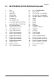
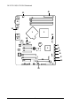
Introduction 1-3 GA-5YXS1-RH/GA-5YXS-RH Motherboard Components 1. 2. 3. 4. 5. 6. 7. CPU Intel 3200 Intel ICH9R ITE IT8718F-S XGI Volari Z9s VGA Memory Intel 82566DC GbE 22. 23. 24. 25. 26. 27. 28. PCI_1 slot(32bit/33MHz) PCI-E x8 slot PCI-E x8 Slot (x1 bandwidth) PCI-E x8 Slot (x1 bandwidth) IPMI BMC Module solt (optional) DIMM1 DIMM2 8. Intel 82573L GbE (GA-5YXS1-RH) 29. DIMM3 8. Intel 82573V GbE (GA-5YXS-RH) 30. DIMM4 9. 10. 11. 12. 13. 14. 15. 16. 17. 18. 19. 20. 21.
English GA-5YXS1-RH/GA-5YXS-RH Motherboard 40 41 31 30 29 28 27 32 33 34 1 2 35 39 36 38 8 7 25 37 43 24 6 3 4 23 5 13 14 15 16 22 17 21 10 42 26 19 11 12 18 9 20 8
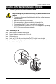
Hardware Installation Process Chapter 2 Hardware Installation Process 2-1 Installing Processor and CPU Haet Sink Before installing the processor and cooling fan, adhere to the following cautions: 1. The processor will overheat without the heatsink and/or fan, resulting in permanent irreparable damage. 2. Never force the processor into the socket. 3. Apply thermal grease on the processor before placing cooling fan. 4. Please make sure the CPU type is supported by the motherboard. 5.
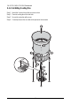
English GA-5YXS1-RH/GA-5YXS-RH Motherboard 2-1-2: Installing Cooling Fan Step 1 Attach the heat sink clip to the processor socket. Step 2 Place the cooling fan on the heat sink. Step 3 Secure the cooing fan with screws.
Hardware Installation Process 2-2 Install Memory Modules Before installing the memory modules, please comply with the following conditions: 1. Please make sure that the memory used is supported by the motherboard. It is recommended that memory of similar capacity, specifications and brand be used. 2. Before installing or removing memory modules, please make sure that the computer power is switched off to prevent hardware damage. 3. Memory modules have a foolproof insertion design.
English GA-5YXS1-RH/GA-5YXS-RH Motherboard Installation Steps: 1. Unlock a DIMM socket by pressing the retaining clips outwards.Aling a DIMM on the socket such that the notch on the DIMM exactly match the notch in the socket. 2. Firmly insert the DIMMinto the socket until the retaining clips snap back in place. NOTE!! We recommened you to populate the same device size on each socket and the same DIMM size. 4. Reverse the installation steps if you want to remove the DIMM module.
Hardware Installation Process 2-3 Connect ribbon cables, cabinet wires, and power supply 2-3-1 : I/O Back Panel Introduction 13
English GA-5YXS1-RH/GA-5YXS-RH Motherboard PS/2 Keyboard and PS/2 Mouse Connector To install a PS/2 port keyboard and mouse, plug the mouse to the upper port (green) and the keyboard to the lower port (purple). Serial Port This connector supports 1 standard COM port, device like modem can be connected to Serial port. VGA Port Connect the monitor cable to this port.
Connector Introduction 2-4 Connectors Introduction & Jumper Setting 2 1 17 16 15 18 5 21 20 4 19 14 11 12 6 7 8 9 10 3 13 1. ATX2 2. ATX1 12. USB3 (USB cable connector) 13. HDDBPB1 3. IDE1 (IDE cable connector) 4. FDC1 (Floppy cable connector) 14. IPMB1 15. FAN1 (CPU fan cable connector) 5. SATA_1 (SATA cable connector) 6. SATA_2 (SATA cable connector) 16. FAN2 (System fan cable connector) 17. FAN3 (System fan cable connector) 7. SATA_3 (SATA cable connector) 8.
English GA-5YXS1-RH/GA-5YXS-RH Motherboard 1/2) ATX2/1 (24-pin/4-pin ATX power connector) With the use of the power connector, the power supply can supply enough stable power to all the components on the motherboard. Before connecting the power connector, please make sure that all components and devices are properly installed. Align the power connector with its proper location on the motherboard and connect tightly. The ATX_12V power connector mainly supplies power to the CPU.
Connector Introduction 3 ) IDE1 (IDE cable connector) An IDE device connects to the computer via an IDE connector. One IDE connector can connect to one IDE cable, and the single IDE cable can then connect to two IDE devices (hard drive or optical drive). If you wish to connect two IDE devices, please set the jumper on one IDE device as Master and the other as Slave (for information on settings, please refer to the instructions located on the IDE device).
English GA-5YXS1-RH/GA-5YXS-RH Motherboard 5/ 6/ 7/ 89/10 ) SATA_ 1~6 (Serial ATA cable connectors) SATA 3Gb/s can provide up to 300 MB/s transfer rate. Please refer to the BIOS setting for the SATA 3Gb/s and install the proper driver in order to work properly. Pin No. 1 2 3 4 5 6 7 7 1 Definition GND TXP TXN GND RXN RXP GND 11/ 12 ) USB2/USB3 (USB cable connectors) Be careful with the polarity of the front USB connector.
Connector Introduction 13 ) HDDBPB1 (SMBUS connector for power supplyr) 1 Pin No. Definition 1 2 SCL SDA 3 4 DETECT HDD LED 5 6 INT GND 14 ) IPMB1 (IPMB connector) 1 Pin No.
English GA-5YXS1-RH/GA-5YXS-RH Motherboard 15/ 16/ 17 ) FAN1 (CPU fan / System fan cable connectors) The cooler fan power connector supplies a +12V power voltage via a 3-pin/4-pin(CPU_FAN) power connector and possesses a foolproof connection design. Most coolers are designed with color-coded power connector wires. A red power connector wire indicates a positive connection and requires a +12V power voltage. The black connector wire is the ground wire (GND).
Connector Introduction 16 ) F_Panel (2X13 Pins Front Panel connector) Please connect the power LED, PC speaker, reset switch and power switch of your chassis front panel to the F_PANEL connector according to the pin assignment above. 2 1 Pin No. 1. 2. 3. 4. 5. 6. 7. 8. 9. 10. 11. 12. 13. 14. 15. 16. 17. 18. 19. 20. 21. 22. 23. 24. 25. 26.
English GA-5YXS1-RH/GA-5YXS-RH Motherboard 20 ) CLR_CMOS1 (Clear CMOS jumper) You may clear the CMOS data to restore its default values by this jumper. Default value doesn’t include the “Shunter” to prevent from improper use this jumper. To clear CMOS, temporarily short 2-3 pin.
Jumper Setting 21 ) RECCOVERY1 ( BIOS recovery jumper) 1 1 1-2 Close: Enable BIOS Recovery function.
2-5 Block Diagram INTEL LGA775 CLOCK GENERATOR ICS9LPR502 Xeon Wolfdale/Concore/ VRD 11.0 ISL6306/6326CR Kentsfield/Yorkfield FSB 1333/1066/800 CHANNEL A DDR2 667/800 Un-Buffered ECC DIMM x 2 PCIE x8 PCIE x8 Slot MCH BIGBY-V (INTEL 3200) DMI_PN_0~3 Control Bus PCIE x8 Slot PCIE x1 PCIE x8 Slot PCIE x1 CHANNEL B DDR2 667/800 Un-Buffered ECC DIMM x 2 DMI SATA x 6 PCIE x1 PCI32/33MHz PCI32/33MHz SPI 8MB Flash USB2.0 USB2.
BIOS Setup Chapter 3 BIOS Setup BIOS Setup is an overview of the BIOS Setup Program. The program that allows users to modify the basic system configuration. This type of information is stored in battery-backed CMOS RAM so that it retains the Setup information when the power is turned off. ENTERINGSETUP Power ON the computer and press immediately will allow you to enter Setup.
GA-5YXS1-RH/GA-5YXS-RH Motherboard GETTINGHELP Main Menu The on-line description of the highlighted setup function is displayed at the bottom of the screen. Status Page Setup Menu / Option Page Setup Menu Press F1 to pop up a small help window that describes the appropriate keys to use and the possible selections for the highlighted item. To exit the Help Window press . Select the Load Setup Defaults item in the BIOS Exit Setup menu when somehow the system is not stable as usual.
BIOS Setup Main Once you enter Phoenix BIOS Setup Utility, the Main Menu (Figure 1) will appear on the screen. Use arrow keys to select among the items and press to accept or enter the sub-menu. Figure 1: Main System Time The time is calculated based on the 24-hour military time clock. Set the System Time (HH:MM:SS) System Date Set the System Date. Note that the “Day” automatically changed after you set the date.
GA-5YXS1-RH/GA-5YXS-RH Motherboard SATA Port 1/2/3/4/5/6 The category identifies the types of Serial SATA hard disk from drive 1 to 6 that has been installed in the computer. System will automatically detect HDD type. Note that the specifications of your drive must match with the drive table. The hard disk will not work properly if you enter improper information for this category. Hard drive information should be labled on the outside device casing. Enter the appropriate option based on this information.
BIOS Setup Advanced Processor Options Figure 1-1: Advanced Processor Option Advanced Processor Option This category includes the information of CPU Speed, Processor CPUID and Processor L2 Cache. Setup menu for C1 Enhanced Mode, No Execute Mode Memory Protection, Intel EIST Support, and PECI Interface. C1 Enhanced Mode With enabling C1 Enhanced Mode, all loical processors in the physical processor have entered the C1 state, the processor will reduce the core clock frequency to system bus ratio and VID.
GA-5YXS1-RH/GA-5YXS-RH Motherboard Intel EIST Support Select the Power Management desired: Enabled C states and GV1/GV3 are enabled. (Default setting) C States Only GV1/GV3 are disabled. GV1/GV3 Only C states are disabled. Disabled C states and GV1/GV3 are disabled. PECI Interface The Platform Environmental Control Interface (PECI Interface) is designed specifically to convey system management information from the processor.
BIOS Setup Advanced About This Section: Advanced With this section, allowing user to configure your system for basic operation. User can change the Memory Configuration, PCI Configuration, I/O Configuration, Advanced Chipset Control and Hardware Monitor.
GA-5YXS1-RH/GA-5YXS-RH Motherboard Memory Configuration Figure 2-1: Memory Configuration Installed Memory/Available to OS/Used by devices/ DIMM Group 1,2,3,4 Status These category is display-only which is determined by POST (Power On Self Test) of the BIOS. &Clear Mem. ECC Err Info Yes Clear the memory status. No Disable this function. (Default setting) Extended RAM Step Enabled Enable test extended memroy process. Disabled Disable this function.
BIOS Setup PCI Configuration Figure 2-2: PCI Configuration Embedded NIC Onboard LAN1 Control Enabled Enable onboard LAN device. (Default setting) Disabled Disable this function. LAN1 Option ROM Enabled Enableing this item to initialize device expansion ROM. Disabled Disable this function. (Defualt setting) Onboard LAN2 Control Enabled Enable onboard LAN device. (Default setting) Disabled Disable this function. LAN2 Option ROM Enabled Enableing this item to initialize device expansion ROM.
GA-5YXS1-RH/GA-5YXS-RH Motherboard PCI Slot 1/2/3/4/5 Option ROM Enabled Enableing this item to initialize device expansion ROM. (Defualt setting) Disabled Disable this function.
BIOS Setup I/O Device Configuration Figure 2-3: I/O Device Configuration Serial Port A This allows users to configure serial prot A by using this option. Enabled Enable the configuration (Default setting) Disabled Disable the configuration. Base I/O Address/IRQ 3F8/IRQ4 Set IO address to 3F8/IRQ4. (Default setting) 2F8/IRQ3 Set IO address to 2F8/IRQ3. 3E8/IRQ4 Set IO address to 3E8/IRQ4. 2E8/IRQ3 Set IO address to 2E8/IRQ3.
GA-5YXS1-RH/GA-5YXS-RH Motherboard Base I/O Address/IRQ 3F8/IRQ4 Set IO address to 3F8/IRQ4. 2F8/IRQ3 Set IO address to 2F8/IRQ3. (Default setting) 3E8/IRQ4 Set IO address to 3E8/IRQ4. 2E8/IRQ3 Set IO address to 2E8/IRQ3. USB Controller This item allows users to enable or disable the USB device by setting item to the desired value. Enabled Enable USB controller. (Default setting) Disabled Disbale this function. Legacy USB Support This option allows user to function support for legacy USB.
BIOS Setup driver supports AHCI mode. Disabled Disabled this function. SATA RAID Enable Enabled Enabled SATA RAID function. Disabled Disable this function.
GA-5YXS1-RH/GA-5YXS-RH Motherboard Advanced Chipset Control Figure 2-4: Advanced Chipset Control Enable Multimedia Timer Yes Enable Multimedia Timer support. (Default setting) No Disable this function.
BIOS Setup Hardware Monitor Figure 2-5: Hardware Monitor CPU / Motherboard Temperature Display the current CPU temperature, Motherboard, and Ambient temperature. Voltage Monitor: DDR1V8, VCC3, VCORE, 0V9, 5V Detect system's voltage status automatically. FAN Monitor: CPU FAN/ Front FAN/ System FAN (RPM) Display the current System 1/2 and CPU fan speed.
GA-5YXS1-RH/GA-5YXS-RH Motherboard Boot -time Diagnostic When this item is enabled, system will shows Diagnostic status when system boot. Enabled Enable Boot-time Diagnostic. Disabled Disable this function. (Default setting) Reset Configuration Data Yes Reset all configuration data. No Do not make any changes. (Default setting) NumLock This option allows user to select power-on state for NumLock. On Enable NumLock. Off Disable this function.
BIOS Setup Security About This Section: Security In this section, user can set either supervisor or user passwords, or both for different level of password securities. In addition, user also can set the virus protection for boot sector. Figure 3: Security Set User Password You can only enter but do not have the right to change the options of the setup menus. When you select this function, the following message will appear at the center of the screen to assist you in creating a password.
GA-5YXS1-RH/GA-5YXS-RH Motherboard Set Supervisor Password You can install and change this options for the setup menus. Type the password up to 6 characters in lengh and press . The password typed now will clear any previously entered password from the CMOS memory. You will be asked to confirm the entered password. Type the password again and press . You may also press to abort the selection and not enter a specified password or press key to disable this option.
BIOS Setup Server Figure 4: Server 43
GA-5YXS1-RH/GA-5YXS-RH Motherboard System Management Figure 4-1: System Management Server Management This category allows user to view the server management features. Including information of BIOS Version. All items in this menu cannot be modified in user’s mode. If any items require changes, please consult your system supervisor.
BIOS Setup Console Redirection Figure 4-2: Console Redirection BIOS Redirection Port If this option is set to enabled, it will use a port on the motherboard. Serial Port A Use Serial Port A as he COM port address. Serial Port B Use Serial Port B as he COM port address. Disabled Disable this function. (Default setting) Baud Rate This option allows user to set the specified baud rate. Options 300, 1200, 2400, 9600, 19.2K, 38.4K, 57.6K, 115.2K.
GA-5YXS1-RH/GA-5YXS-RH Motherboard Flow Control This option provide user to enable the flow control function. None Not supported. XON/OFF Software control. CTS/RTS Hardware control. (Default setting) Terminal Type This option allows user to select the specified terminal type. This is defined by IEEE.
BIOS Setup Assert NMI on SERR If thisoption is set to enabled, PCI bus system error (SERR) is enabled and is routed to NMI. Enabled Enable Assert NMI on SERR. (Default setting) Disabled Disable this function. Post Error Pause If this item is set to enabled, the system will wai for user intervention on critical POST errors. If this item is disabled, the system will boot with no intervention if possible. Enabled Enable Post Error Pause. (Default setting) Disabled Disable this function.
GA-5YXS1-RH/GA-5YXS-RH Motherboard Boot Figure 5: Boot Boot Priority Order This field determines which type of device the system attempt to boot from after PhoenixBIOS Post completed. Specifies the boot sequence from the available devices. If the first device is not a bootable device, the system will seek for next available device. Key used to view ot configure devices: Up and Down arrows select a device. <+> and <-> moves the device up or down. and specifies the device fixed or removable.
BIOS Setup Exit Figure 6: Exit About This Section: Exit Once you have changed all of the set values in the BIOS setup, you should save your changes and exit BIOS setup program. Select “Exit” from the menu bar, to display the following sub-menu.
GA-5YXS1-RH/GA-5YXS-RH Motherboard Exit Saving Changes This option allows user to exit system setup with saving the changes. Press on this item to ask for the following confirmation message: Pressing ‘Y’ to store all the present setting values tha user made in this time into CMOS. Therefore, whenyou boot up your computer next time, the BIOS will re-configure your system according data in CMOS.
BIOS Setup Exit Discarding Changes This option allows user to exit system setup without changing any previous settings values in CMOS. The previous selection remain in effect. This will exit the Setup Utility and restart your compuetr when selecting this option.
GA-5YXS1-RH/GA-5YXS-RH Motherboard Load Settup Default This option allows user to load default values for all setup items.
BIOS Setup Discard Changes This option allows user to load previos values from CMOS for all setup item.
GA-5YXS1-RH/GA-5YXS-RH Motherboard Save Changes This option allows user to save setup dat ato CMOS. When you press on this item, you will get a confirmation dialog box with a message as below: Press [Yes] to save setup daya to CMOS.