
User Manual
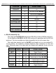


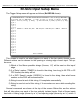


c) DE-09 Nine Position Male:
On the eight port Br-SDC8, these eight male connections are used to attach
the devices that receive the strings that the Br-SDC8 generates or reroutes.
A nine pin male to nine pin female serial cable with ʻstraight throughʼ wiring
should be used to connect the Br-SDC to your controlled devices. The pins that
the Br-SDC uses are:
POSITION
WIRE #
SIGNAL NAME:
TOP-RIGHT
TOP-LEFT
BOTTOM-RIGHT
BOTTOM-LEFT
1
n/c
2
RS-232 Rx to Br-SDC8
3
RS-232 Tx from Br-SDC8
4
n/c
5
Ground
6
n/c
7
n/c
8
n/c
9
n/c
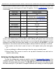
1/4-J6 Input:
This connector has eight optically isolated inputs. It requires an external power
source. It is compatible with the digital outputs from any Gilderfluke & Company Show
Control Systems.
External Power
(Brown) PIN #1
(red) PIN #2
(orange) PIN #3
(yellow) PIN #4
(green) PIN #5
(blue) PIN #6
(violet) PIN #7
(grey) PIN #8
(white) PIN #9
(black) PIN #10
GROUND
DATA BIT 7
DATA BIT 6
DATA BIT 5
DATA BIT 4
DATA BIT 3
DATA BIT 2
DATA BIT 1
DATA BIT 0
+ 5 to 24 VDC SUPPLY
Gilderfluke & Co.• 205 South Flower Street • Burbank, California 91502 • 818/840-9484 • 800/776-5972 • fax 818/840-9485
Br-SDC Manual / December 30, 2013 9:24 AM / page 12 of 62