
Owner's manual

- QUAD D/A and SERVO MOTOR CONTROLLER CONNECTIONS -
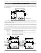
The quad D/A converters get their data and power through a single J-6 data cable. The analog out-
put is available on a 1/4 J6/A analog output connection. The pin out for this connector is as follows:
Pin #1 GROUND
Pin #2 UNREGULATED 12 VDC (fused at 1 amp)
Pin #3 + CHANNEL 4 (03H) ANALOG OUTPUT
Pin #4 - CHANNEL 4 (03H) REFERENCE
Pin #5 + CHANNEL 3 (02H) ANALOG OUTPUT
Pin #6 - CHANNEL 3 (02H) REFERENCE
Pin #7 + CHANNEL 2 (01H) ANALOG OUTPUT
Pin #8 - CHANNEL 2 (01H) REFERENCE
Pin #9 + CHANNEL 1 (00H) ANALOG OUTPUT
Pin #10 - CHANNEL 1 (00H) REFERENCE
The GROUND and 12 VDC outputs are used to supply power to a Quad EFB (Electronic FeedBack)
servo controller when it is used with the Quad D/A. They can also be used to feed in 15 VDC from an
auxiliary power supply if needed. In most user applications, these two outputs won't be needed. The
negative reference outputs for all four channels are connected in common inside the Quad D/A. If your
application requires it, a single negative reference wire may used for all four channels.
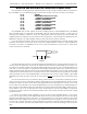
If you are using servo motors, these are connected to the standard three pin sockets used by many
brands of servo motors. Some newer servo motors use a slightly different connector, and an adapter for
this style of connector is available from the servo motor manufacturers. The pin out for these servo
motor connections is as follows:
SIGNAL
SERVO
+ SUPPLY
SERVO
- SUPPLY
The last remaining connector is for attaching the power supply which is used to power the servo mo-
tors. The power for these must come from an external source as they can potentially use a lot more cur-
rent than the animation system can normally supply. Most servo motors run from a voltage between 3.5
volts and 7.5 volts. The lower the voltage the less strength and speed a given servo motor will have. A
higher voltage will give that same servo motor greater speed and strength. In some cases a lower speed
is desired for the smoothness of the movement, while in other cases the need for high speed or strength
may be paramount. The chief disadvantages of running the servo motors in high voltage / high speed
applications are that the servo motor will run hotter and is much more likely to have a mechanical fail-
ure.
The size of the servo motor, the load it is driving, and the amount of movement it is doing can all ef-
fect the amount of current it will require. Most of the smaller servo motors draw about an amp of current
at stall (This is when the servo motor shaft is held against the motor's best efforts to move it.). This condi-
tion isn't often encountered in any real world applications, but if you are planning on really abusing your
servo motors you should allow about an amp per motor when selecting a power supply. Under most nor-
mal conditions, 1/4 to 1/2 an amp per servo motor will be sufficient. If your power supply is undersized,
you will see a certain amount of interaction between servo motors when a number of them are moving
at the same time.
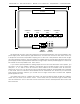
To reduce the number of wires needed to run into a servo motor-controlled figure it is not uncom-
mon to run the high current power supply leads directly from the power supply to the servos in the figure
and gang the signal lines. When this is done, it is still necessary to run low current leads from the power
supply to the power supply connections on the quad D/A board. If the signal line runs to the servo mo-
tors are long, it may be necessary to use shielded lines to prevent noise and cross-talk between the ser-
vos. You can tell when you have this problem when some servo motors are tending to jitter uncontrol-
lably.
GILDERFLUKE & CO. ¥ 205 SOUTH FLOWER ST. ¥ BURBANK, CALIF. 91502-2102 ¥ 818/840-9484 ¥ FAX818/840-9485
3