
Owner's manual
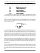
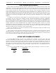

CHANNEL 1
(00H)
FULL
SCALE
MIN.
SCALE
CHANNEL 2
(01H)
FULL
SCALE
MIN.
SCALE
CHANNEL 3
(02H)
FULL
SCALE
MIN.
SCALE
CHANNEL 4
(03H)
FULL
SCALE
MIN.
SCALE
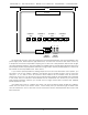
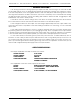
J-6 INPUT
1/4 J-6A
OUTPUT
SERVO
MOTOR
POWER IN
SERVO
MOTOR
OUTPUTS
3210
4"
5 5/16"
Be aware that the servo motor input signals are notoriously bad travelers. They are susceptible to any
power supply noise, radio frequency (RF) interference, and even the noise from other servo motors. Try
to keep these lines as short as possible. Anything over 10 feet can cause problems. Even shorter lengths
can have problems under the right circumstances. Possible solutions include large capacitors across the
power supply leads and pullup resistors between the signal input and the positive supply line. These must
be located as close as possible to the servo motors.
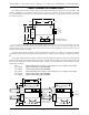
If you need to optically isolate the analog outputs from the rest of the animation control system, you
will need to cut the four 1N4001 diodes D1 through D4 (the four diodes closest to the J6 connector)
and pins 1, 11, 21, and 31 on the J6 connector. This is easiest to do on the back of the J6 connector,
rather than on the front. You will need to use an external power supply for the Quad D/A when operating
in this mode. The four channels of the Quad D/A are not isolated from one another. If you need com-
plete isolation between channels, you should use four single channel D/A converters with separate
power supplies for each.
The Quad D/A comes in a plastic case which can be mounted by simply double face taping it
where ever you need. If you need to mount it more solidly, then put screws through the back of the
case as needed. The front of the case can be removed for service and adjustment after the box has
been mounted.
GILDERFLUKE & CO. ¥ 205 SOUTH FLOWER ST. ¥ BURBANK, CALIF. 91502-2102 ¥ 818/840-9484 ¥ FAX818/840-9485
4