
Owner's manual

- D/A CONVERTER ADJUSTMENTS -
Each channel of every D/A converter has two adjustments. One of these two sets the level of the
output when a minimum scale digital input (00H) is sent to the D/A, while the other sets the level of the
output when a full-scale (FFH) signal is sent to it. Both of these adjustments are completely independent
of one another. Moving one doesn't affect the other, although it does change the positions of all the
steps in between the two. Either of these setting may be adjusted to put it anywhere in the 0 to 10 VDC
output range. Adjusting the minimum scale level above that of the full scale level has the effect of 're-
versing' the movement. By doing this the output can be set so that a full scale signal will be at a lower
voltage than a minimum scale signal. All D/A converters are factory calibrated to 0 to 10 VDC before
shipping.
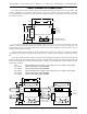
To adjust the full and minimum scale outputs, you need to send either a full or minimum scale signal
to the D/A. This can come from a Micro Console, Full-sized Programming Console, Togglodyte,
Hand/Off/Auto (HOA) test switches, or a number of other sources. You then adjust the appropriate trim-
pot on the D/A board to set the desired level (Full scale trimpot if you are sending a full scale signal, min-
imum scale trimpot if you are sending a minimum scale signal). If you are setting the signal to a desired
voltage, measure the output voltage between the negative and positive output connector on the D/A
and adjust the trimpot until the signal is at the desired level. If you are adjusting the signal for setting the
end points of a mechanical movement or servo motor, you simply need to watch the movement and
adjust the trimpot until the movement is at the desired position.
When one end position is set, send the opposite full scale command to the D/A and adjust the ap-
propriate trimpot to set that end too.
Some caution must be used when adjusting servo motors or mechanical movements which may be
damaged by being commanded to go to a position beyond that which they are designed to move. In
these cases it is sometimes best to adjust both the full and minimum scale trimpots to a center position
for the movement and then adjust them slowly outward from there.
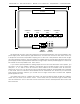
- ATCHLEY MFB CYLINDER ATTACHMENT -
An Atchley MFB actuator is a type of air cylinder which includes a jet pipe servo valve and
Mechanical FeedBack (i.e. MFB) system. It is used when there is a need for a strong, reliable, and simple
analog mechanical movement. The cylinder needs only be fed a 80 to 100 PSI supply of clean dry air
and a 0 to 10 VDC control signal. When given a 0 volt input, the cylinder will retract. When fed a 10
VDC signal, the cylinder will extend. If fed a 5 VDC signal, the cylinder will go to a mid-stroke position.
The MFB will follow a changing input voltage smoothly, reliably, and with a remarkable amount of
strength.
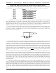
To connect an Atchley MFB actuator to a D/A converter, use the following to connect it's four wires:
ATCHLEY WIRES CONNECT TO:
RED ATTACH TO GREEN
GREEN ATTACH TO RED
YELLOW + OUTPUT FROM D/A
WHITE - REFERENCE FROM D/A
GILDERFLUKE & CO. ¥ 205 SOUTH FLOWER ST. ¥ BURBANK, CALIF. 91502-2102 ¥ 818/840-9484 ¥ FAX818/840-9485
5