
Manual
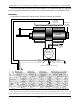

EFB-Quad and PID-Quad Inputs:
The inputs to the EFB-Quad and PID-Quad are a standard 1/4 J6/A cables. This typically comes from a
BS-ANA or other analog output control system. It is fed to the feedback card through the ten position
ribbon cable connector.
The pinout for the 1/4 J6/A is as follows:
1 brown circuit ground
2 red 15 to 24 VDC Power Supply
3 orange Channel 3 Positive Analog Input
4 yellow Channel 3 Negative Reference
5 green Channel 2 Positive Analog Input
6 blue Channel 2 Negative Reference
7 violet Channel 1 Positive Analog Input
8 gray Channel 1 Negative Reference
9 white Channel 0 Positive Analog Input
10 black Channel 0 Negative Reference
The ‘positive analog inputs’ are typically 0 to 10 VDC, referenced to the ‘negative references’. This
‘negative reference is nominally at about 1 1/2 volts above the ground level, and is common for all four
channels. This reference is provided by the analog outputs of all Gilderfluke & Company Animation
Control Systems. If you are using these feedback cards with another control system, you will need to
supply this reference voltage along with the 15 to 24 VDC supply. If the negative reference is attached
to the real ground, the card will not operate properly.
GILDERFLUKE & CO. • 205 SOUTH FLOWER ST. • BURBANK, CALIF. 91502-2102 • 818/840-9484 • FAX818/840-9485
7 of 12