Model# FW6AC012CP OMS THD SKU# 1001381674 OMSID# 206614275 INSTALLATION AND CARE GUIDE WIDESPREAD LAVATORY FAUCET Questions, problems, missing parts? Before returning to the store, call Glacier Bay Customer Service 8 a.m. - 7 p.m., EST, Monday - Friday 9 a.m. - 6 p.m., EST, Saturday 1-855-HD-GLACIER (1-855-434-5224) HOMEDEPOT.COM/GLACIERBAY THANK YOU We appreciate the trust and confidence you have placed in Glacier Bay through the purchase of this lavatory faucet.
Table of Contents Important Information...............................2 Warranty....................................................2 Pre-Installation..........................................2 Planning Installation............................2 Tools and Hardware Required.............2 Package Contents................................3 Installation.................................................4 Operation...................................................9 Care and Cleaning................................
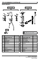
Pre-Installation (continued) PACKAGE CONTENTS Faucet Assembly Drain Assembly A P* L* J S K B* M* C* D* R F* G* H* E* Q N* I O* Tool T Part Description NOTE: *Items come pre-assembled.
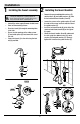
Installation 1 Installing the faucet assembly 2 Installing the faucet handles □□ Remove the preassembled guide washers (E), metal washers (D) and rubber washers (C) from the hot and cold faucet handles (A and K). □□ Loosen the screws on the guide washers (E) until the ends of the screws are flush with the face of the guide washers (E). □□ Insert the hot faucet handle (A) to the left of the spout and cold faucet handle (K) to the right of the spout.
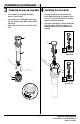
Installation (continued) 3 Preparing the pop-up assembly 4 Installing the drain body □□ Insert the drain assembly (M) and rubber washer (L) into the sink. □□ Secure the drain assembly (M) in place under the sink using the large rubber washer (N) and lock nut (O). □□ Opening for ball rod must face towards rear of sink. □□ Insert the plunger (P) into the sink with the plastic loop of the plunger (P) facing the rear of the sink. This ensures the plunger is in locked mode and cannot be removed.
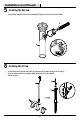
Installation (continued) 5 Installing the ball rod □□ Insert the ball rod (Q) into the drain assembly (M). Tighten the ball nut on the ball rod (Q). Q 1 M 2 6 Installing the lift rod □□ Insert the lift rod (S) through the faucet (J) and attach the lift rod strap (R) to the lift rod (S). □□ Push the button on the lift strap (R) to allow the lift rod (S) to slide through. □□ Release to lock.
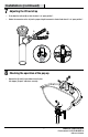
Installation (continued) 7 Adjusting the lift rod strap □□ Push down the ball rod (Q) so that the drain is at “open position”. □□ Rotate the connector on the strip to the proper height to connect to the ball rod when it is at “open position”. Q 1 2 3 8 Checking the operation of the pop up □□ Operate the lift rod (S) up and down to verify that the stopper (P) opens and closes correctly. S P 7 HOMEDEPOT.COM/GLACIERBAY Please contact 1-855-HD-GLACIER for further assistance.
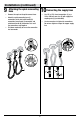
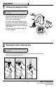
Installation (continued) the quick connecting 9 Attaching 10 Connecting the supply lines hose □□ Remove the cap from the quick connect hose. □□ Attach the quick connecting hose (I) connections to the hot faucet handle (A) connection, faucet body (J) connection, and cold faucet handle (K) connection. Push until the connections snap together. □□ Pull down moderately to ensure the connection has been made. □□ Use 1/2 in. I.P.S. faucet connections (1), or a 3/8 in. O.D.
Operation 1 Flushing and checking for leaks IMPORTANT: After installation is complete, remove the aerator to flush the water lines. Do not lose the gasket in the aerator. A □□ Ensuring the handles are in the off position, turn on the water supply and check for leaks. If you discover any leaks, check your connections to ensure they are installed properly. □□ Use a wrench (T) to remove the aerator (B) from the faucet (J). Turn on the hot and cold handles to allow the water to run for at least one minute.
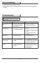
Care and Cleaning □□ To clean, wipe down with a damp cloth and towel dry. □□ Do not use abrasive cleaners, steel wool, or harsh chemicals when cleaning this faucet, or the warranty will be voided. Troubleshooting NOTE: Refer to the service parts section in this manual for a detailed drawing showing the location of the parts listed below. Problem Possible Cause Solution There are leaks from the handle. □□ The bonnet nut is loose. □□ Tighten the bonnet nut.
Service Parts 1. 2. 15. 3. 17. 5. 11. 6. 4. 16. 12. 8. 13. 7. 14. DO NOT REMOVE DATE CODE: HOT 9. 1-888-328-2383 18. Faucet ID Tags can be found on the hot supply line. Part Description 19. 10. Part No.
Questions, problems, missing parts? Before returning to the store, call Glacier Bay Customer Service 8 a.m. - 7 p.m., EST, Monday - Friday 9 a.m. - 6 p.m., EST, Saturday 1-855-HD-GLACIER (1-855-434-5224) HOMEDEPOT.COM/GLACIERBAY Retain this manual for future use.
Núm. de modelo FW6AC012CP OMS THD SKU# 1001381674 OMSID# 206614275 GUÍA DE INSTALACIÓN Y CUIDADO GRIFO PARA LAVABO CON MANIJAS DE ABERTURA AMPLIA ¿Tiene preguntas, problemas, o faltan piezas? Antes de regresar a la tienda, llame a Servicio al Cliente de Glacier Bay de lunes a viernes de 8 a.m. a 7 p.m., hora local del Este de lunes a viernes de 9 a.m. a 6 p.m., sábado 1-855-HD-GLACIER (1-855-434-5224) HOMEDEPOT.
Tabla de Contenido Información Importante........................... 2 Garantía.....................................................2 Pre-instalación......................................... 2 Planificación de la Instalación.............2 Herramientas y Piezas Necesaria........2 Contenido del Paquete........................3 Instalación.................................................4 Operación...................................................9 Cuidado y Limpieza.................................
Pre-instalación (continuación) CONTENIDO DEL PAQUETE Faucet Assembly Drain Assembly A P* L* J S K B* M* C* D* R F* G* H* E* Q N* I O* Herramienta T Pieza Descripción NOTA: *Las piezas vienen preensambladas.
Instalación del conjunto del conjunto del 2 Preparación 1 Instalación levadizo grifo □□ Retire las arandelas guía (E), las arandelas metálicas (D) y las arandelas de goma (C) preensambladas de las manijas de agua caliente y fría del grifo (A y K). □□ Afloje los tornillos de las arandelas guía (E) hasta que los extremos de los tornillos estén a nivel con la superficie de las arandelas guía (E).
Instalación (continuación) del conjunto 3 Preparación levadizo 4 Instalación del desagüe □□ Inserte el tubo de desagüe (M) y arandela de goma (L) en el fregadero □□ Fije el tubo de desagüe (M) en su lugar debajo del fregadero con grande arandela de goma (N) y contratuerca (O) □□ La abertura para la varilla de rótula debe quedar frente a la parte posterior del lavabo. □□ Inserte el tapón principal (P) en el fregadero con el bucle de plástico del tapón principal (P) hacia la parte posterior del fregadero.
Instalación (continuación) 5 Instalación de la varilla de bola □□ Inserte la varilla glóbulo (Q) en el tubo de desagüe (M). Apretar la tuerca de bola en la varilla glóbulo (N). Q 1 M 2 6 Instalación de la varilla elevación □□ Inserte la varilla de elevación (S) a través del grifo e instale la varilla levadiza (R) en la varilla de elevación. □□ Presione el botón de varilla levadiza (R) para permitir que la va elevación (S) se deslice a través. □□ Libérelo para bloquear la varilla en su posición.
Instalación (continuación) 7 Ajuste de la correa de la barra de elevación □□ Empuje hacia abajo la varilla de bola (Q) para que el desagüe está en la “posición abierta”. □□ Gire el conector de la palanca a la altura adecuada para conectarlo a la varilla de bola cuando esté en la “posición abierta”. Q 1 2 3 del funcionamiento del mecanismo 8 Verificación levadizo □□ Opere la barra de elevación (S) hacia arriba y hacia abajo para verificar que el émbolo principal (P) se abra y cierre correctamente.
Instalación (continuación) de la manguera de de las líneas de 9 Sujeción 10 Conexión conexión rápida suministro de agua □□ Quita la tapa del tubo de conexión rápida. □□ Sujete las conexiones de la manguera de conexión rápida (I) a la conexión de la manija de agua caliente(A), a la conexión del cuerpo del grifo (J) y a la conexión de la manija de agua fría (K). Empuje hasta que las conexiones encajen bien. □□ Jale hacia abajo moderadamente para comprobar que se ha hecho la conexión.
Operación 1 Enjuague y verificación de fugas IMPORTANTE: Una vez terminada la instalación, retire el aireador para enjuagar los conductos de agua. No pierda el empaque del aireador. □□ Compruebe que la manija esté en posición cerrada. Abra la alimentación de agua y compruebe si hay fugas. De haberlas, verifique que las conexiones estén bien hechas. □□ Use una llave (T) para quitar el aireador (B) del grifo (J). Levante la manija para que el agua corra al menos durante un minuto.
Cuidado y Limpieza □□ Limpie con un trapo húmedo y seque con un paño. □□ No use limpiadores abrasivos, lana metálica ni productos químicos fuertes para limpiar el grifo o la garantía podría anularse. Solución de Problemas NOTA: Consulte la sección de piezas de repuesto de este manual para ver dibujos detallados sobre la ubicación de las piezas enumeradas abajo. Problema Posible causa Solución Hay fugas por la manija. □□ La tuerca tapa está floja. □□ Apriete la tuerca tapa.
Piezas de Repuesto 1. 2. 15. 3. 17. 5. 11. 6. 4. 16. 12. 8. 13. 7. 14. DO NOT REMOVE DATE CODE: HOT 9. 1-888-328-2383 18. Las etiquetas de identificación del grifo se encontrarán en la tubería de alimentación de agua caliente. Pieza Descripción 19. 10. Pieza No. Pieza Descripción Pieza No.
¿Tiene preguntas, problemas, o faltan piezas? Antes de regresar a la tienda, llame a Servicio al Cliente de Glacier Bay de lunes a viernes de 8 a.m. a 7 p.m., hora local del Este de lunes a viernes de 9 a.m. a 6 p.m., sábado 1-855-HD-GLACIER (1-855-434-5224) HOMEDEPOT.COM/GLACIERBAY Conserve este manual para uso futuro.