
Installation Guide


4. Depending upon the size of your pool you will also require one of the following tube kits: (Tube Assembly is detailed below)
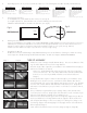
5. Positioning Your Solar Reel:
For Rectangular pools, place Stands at either end of pool. (See Fig. A)
For Irregular shaped pools, place Stands at some convenient midway point. You will need to
fold Blanket and allow Blanket to unwind in two directions. (See Fig. B)
RECTANGULAR
IRREGULAR
Unroll Unroll Unroll
Fig. A
Fig. B
6. Trimming Your Solar Blanket:
•LayyourSolarBlanket(notprovided)ontopofwater.IMPORTANT!IrregularShapedPoolswillneedtohavetheirsolarcovers
foldedatpointofplacementofStands!ThecoverwillunrollleftandrightofStands&crosspole.Pleaseallow6inchesmore
material on length to allow for a fold where straps will be attached for wind onto reel system. (See Fig. B above)
•Withscissorstrimblankettotshapeofpool.Besuretoclearpooledgecoping.
7. Assembling The Tube Kit:
All Tube Sets consist of 6 sided Hexagon shaped aluminum tubing. There are two diameters of tubing, the smaller size nesting
intothelargersize.AllTubeKitsBeginandEndwithSmallTubes.TheTubeInsertRequiresCAREFULALIGNMENT!
All tube kits consist of hexagon shaped aluminum tubing. There are two diameters of tub-a.
ing; the smaller diameter will insert into the larger diameter.
Determine length of tube required for your installation. Note maximum nished length per b.
tube kit size listed above. (In Step 4)
Please note: Smaller diameter tube will be used on both ends of the reel and will
connect to the base unit. Two of the smaller diameter tubes will have predrilled axle
bolt holes on one end. The pre-drilled end will be connected to the base unit.
(Image 1)
Loosely assemble tubes together to match the desired length for your installation, evenly c.
dividing the excess at each connection. Note that the smaller diameter tube must be
inserted a minimum of 9” into the larger diameter tube at each connection. Tip: Measure
in 9” from end of smaller diameter tube and make a mark with a pencil. (Image 2) The
tube must be inserted at least to your pencil mark. It is ok if tube is inserted more than 9”,
but not less.
Once you determine length and have proper spacing of tubes, mark each tube at the d.
connection point for reference. (Image 3) This will eliminate the need to re-measure if your
tubes get moved during the remainder of the installation process.
Each connection will be fastened together with the through bolts supplied in your tube kit. e.
Use the pre-drilled holes in the larger diameter tube as a guide to drill the smaller inner
tube. (Image 4) Twist tubing to remove excess play prior to drilling holes. (Image 5 - Be-
fore Twisting, Image 6 - After Twisting) (Fig.C on last page) Drill from each side with the
drill bit supplied. (Image 7)
Fasten with 2 bolts and nuts at each connection. (Image 8, Image 9, Image 10) f.
TUbE KIT ASSEMbLY:
Image 1
Image 2
Image 3
Image 4
Image 5
Image 6
Image 7
Image 8
Image 9
Image 10
59.5” x 2.75” Dia. Inner Tube
59.5” x 2.95” Dia. Outer Tube
3” Through Bolt with Nut
Drill Bit
Max. nished length = 13’3/8”
72” x 2.75” Dia. Inner Tube
72” x 2.95” Dia. Outer Tube
3” Through Bolt with Nut
Drill Bit
Max. nished length = 16’ 1/2”
59.5” x 2.75” Dia. Inner Tube
59.5” x 2.95” Dia. Outer Tube
3” Through Bolt with Nut
Drill Bit
Max. nished length = 21’ 3/4”
59.5” x 3.75” Dia. Inner Tube
59.5” x 4.0” Dia. Outer Tube
4” Through Bolt with Nut
3.75” Axel Bult with Nut
4” Aluminum Insert
4” Resin Insert
Drill Bit
Maximum length = 21’ 3/4”
68” x 3.75” Dia. Inner Tube
68” x 4.0” Dia. Outer Tube
4” Through Bolt with Nut
3.75” Axel Bult with Nut
4” Aluminum Insert
4” Resin Insert
Drill Bit
Max. nished length = 25’ 3/8”