523 Digital Wattmeter Instruction Manual
GLOBAL SPECIALTIES INSTRUMENTS 1523 2.6KW Autoscan True RMS Power Meter INSTRUCTION MANUAL TABEL OF CONTENTS SECTION DESCRIPT ION PAGE NO.
SECTION - 1 SAFETY INSTRUCTIONS The general safety information in this part of the summary is for both operating and servicing personnel. Specific warnings and cautions will be found throughout the manual where they apply, but may not appear in this summary. 1. 2. 3. 4. This indicates refer to the manual wherever necessary. E/ Indicates Protective Ground Terminal. Indicates Danger ! High Voltage.
SECTION - 2 TECHNICAL SPECIFICATIONS 2.1 Measuring Parameters : True RMS V, A, VA, W and Frequency. 2.2 Measuring Limits a) Voltage b) Current c) Volt Amperes d) Power e) Power Factor f) Frequency 75V to 130V (115V operation). 0.2 to 20A rms AC (40A peak). 16 to 2600VA. 1 to 2600W. 0.5 to unity (No display). 45 to 65Hz. 2.3 : : : : : : Measurement Accuracy a) Voltage / Current : b) Volt Amperes/Power: c) Power Factor : d) Frequency : 0.5% of reading ±1 digit. 1% of reading ±2 digits.
SECTION - 3 GENERAL DESCRIPTION 3.1 INTRODUCTION Global Specialities' 2.6KW AUTOSCAN TRUE RMS POWER METER, MODEL 1523 is a state-ofthe-art instrument, ideal for providing all the information about any electrical load connected to the AC Mains. It monitors/scans sequentially all electrical parameters viz., Voltage, Current, Power, VA, & Mains Frequency, thus providing a clear picture of the load. User operation is very simple.
SECTION - 4 OPERATING INSTRUCTION 4.1 IDENTIFICATION OF CONTROLS 1. V - This key is to display the measured mains rms voltage in Volts on LCD. 2. W - This key is to display the power consumed by load, every second, on LCD. 3. F This key is to display the mains frequncy in Hz on LCD. 4. I / RANGE - This key is to display the rms value of measured load current in Amps on LCD. 5. VA - This key is to display the volt-amp of load on LCD and it is updated every second. 6.
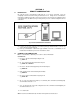
1. Mains In - Cord for delivering Mains Power(115V ac) to the instrument. 2. Output - Socket for plugging in the appliance / load to be monitored.There are 2 socets to share the load of 20A equally. 3. Load Switch - Turns ON/OFF outgoing power to the load.Their are 2 switches for 2 output sockets. 4. Fuse - Protective Fuse between mains & load. 5. RS232 Interface Connector connector. 4.
SECTION - 5 REMOTE COMMUNICATION 5.1 INTRODUCTION By using the remote communication facility and the set of remote commands, a PC can completely control the instrument and get information from it. During remote communication, front panel is disabled (except Go Local key) as long as the remote PC doesn’t relinquish control of the instrument or the GO Local key on front panel is pressed. Follow the diagram below for connections. Fig.
5.3 NOTES REGARDING COMMUNICATION i) Definition of signals on ‘RS232’ interface connector on rear panel (5) for remote communication. Pin No. Signal Source Description 2 RXD Remote PC Receive data from Remote PC 3 TXD Instrument Transmit data to Remote PC 5 Gnd — Signal Gnd ii) Communication parameters Bits per second - 9600 Data bits - 8 Parity - None Stop bits - 1 Flow Control - None iii) The commands to the instrument should be in upper case letters only.
SECTION - 6 TESTING & CALIBRATION PROCEDURE 6.1 TITLE : 6.2 REF. DOCUMENTS : 6.3 EQIPMENTS : Testing & Calibration Procedure of Power Meter 1523 1) 2) 3) 4) 5) 5050Power Meter Test Procedure. Power Meter Voltmeter for AC Voltage & Current Meter up to 20A true RMS type. Variac sourcing current up to 20A. Frequency Counter. Load up to 20A AC. 6.4 PROCEDURE : 6.4.1 Testing of PCBs : 1. Check all the PCBs for dry solder, loose contact of components capacitor polarities & ratings etc. 2.
6.4.5 Testing of Manual & Auto Mode : 1. All the parameters can be viewed with the keys on front panel i.e. V, I, W, VA, F. 2. Compare V & I values on display with standard DMM. Also calculate & compareVA & Power for ( for resistive load power should be equal to VA ). 3. Auto scanning of all parameters can be done by pressing Auto scan / GL key. Auto scanning is done at speed of 1 Sec. To come out of auto scan mode, press any other key. 6.4.
SECTION - 7 PART LIST PCB Components 5051A-MAIN-0306 IRD 551 ======================================================================= Ref Designator Value ======================================================================== RESISTORS R1 470E SMD 0805 CHIP R2 470E SMD 0805 CHIP R3 16E CHIP 1/8W 1206 R4 1K 1% 0805 0.125W SMD R5 10E SMD 0805 CHIP R6 10K SMD 0805 CHIP R7 12K SMD 0805 CHIP R8 470E SMD 0805 CHIP R9 470E SMD 0805 CHIP R10 1K 1% 0805 0.125W SMD R11 1K 1% 0805 0.
PCB Components 5051A-MAIN-0306 IRD 551 ======================================================================= Ref Designator Value ======================================================================== CAPACITORS C16 18nF SMD 0805 C17 100nF / 50V 10% 0805SM C18 10µF / 16V 2010MIL SMD ELE RAD C19 33pF SMD CHIP 0805 C20 33pF SMD CHIP 0805 C21 100nF / 50V 10% 0805SM C22 100nF / 50V 10% 0805SM C27 3300µF / 35V 20% ELE RAD C28 330µF / 25V ELE RAD C29 10µF / 16V 2010MIL SMD ELE RAD C30 100nF / 50V 10% 0805SM C
PCB Components 5051A-RS232-0706 IRD 570 ======================================================================= Ref Designator Value ======================================================================== RESISTORS R1 1K SMD CHIP 1% 0.125W 0805 R2 10K SMD CHIP 0805 R3 200E SMD CHIP 0805 R4 2.4K SMD CHIP 0805 R5 1K SMD CHIP 1% 0.125W 0805 R6 10K SMD CHIP 0805 R7 200E SMD CHIP 0805 R8 2.
PCB Components 5051A-KBD-0306 ======================================================================= Ref Designator Value ======================================================================== SWITCH S1 TO S6 ITTD 6 KEY BOAR DBLACK HEIGHT 6mm CONNECTORS J1 DUAL IN ROW UNLOC MALE STRAIGHT BURGE STRIP, 16 PIN PCB Components LCD ASSY-16X2 HY-1602F-205 YELLOW ======================================================================= Ref Designator Value ========================================================
SERVICE AND WARRANTY INFORMATION For up-to-date product information, please visit www.globalspecialties.com. For instructions on how to obtain a return merchandise authorization number (RMA), please visit our website, or call our customer service department. GLOBAL SPECIALTIES 22820 Savi Ranch Parkway Yorba Linda, CA 92887 800-572-1028 globalspecialties.com Global Specialties will service and repair this instrument free of charge for a period of 3 full years, subject to the warranty conditions below.