
Instruction Manual


SECTION - 6
TESTING & CALIBRATION PROCEDURE
6.1 TITLE : Testing & Calibration Procedure of Power Meter 1523
6.2 REF. DOCUMENTS : 5050Power Meter Test Procedure.
6.3 EQIPMENTS : 1) Power Meter
2) Voltmeter for AC Voltage & Current Meter up to 20A true RMS type.
3) Variac sourcing current up to 20A.
4) Frequency Counter.
5) Load up to 20A AC.
6.4 PROCEDURE :
6.4.1 Testing of PCBs :
1. Check all the PCBs for dry solder, loose contact of components capacitor polarities & ratings
etc.
2. Check for proper contacts of smd resistor networks of 10Kohms, on Main Board.
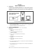
3. Connect all the Boards as per wiring diagrams.
6.4.2 Testing of Power Supply :
1. Switch on the Mains supply ( 115V ) to the unit.
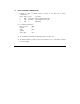
2. Check the various supply voltages on CPU Board such as +5V, -5V at test points TP3 &
TP4 wrt GND & reference voltage with U1-12 should be 2.500V wrt GND.
6.4.3 Power on Display :
Switch on mains. On power on welcome message appears which is as follows :
APLAB MODEL : 1523
TRUE RMS MAINS : POWER METER
VERSION : V 1.00
Now the system carries out eprom-test & initializes the system variables if necessary. On
Successful EPROM test is shown.
EPROM TEST : OK
Else the following message is displayed :
EPROM TEST : FAIL
V : ININ W : IGNOR
If V key is pressed it initializes the eprom. If the system is unable to initialize the eprom, it
displays following message on 2nd line of display:
EPROM ERROR : Else if W key is pressed it ignores EPROM fail. Now Mains voltage screen is
displayed on LCD.
6.4.4 Testing Microcontroller 859S52 :
1. Check for momentary high ( +5V ) pulse at pin 9 (RESET) of 89S52 on power on or pressing
reset switch SW1 on CPU board.
2. Check pin 30 (ALE) of U1 (89S52) to be a pulse signal of 2MHz with counter.
3. Check frequency at TP1 wrt GND to be 2MHz with counter.
4. Keep all other presets & trimmers in middle position. Adjust preset VR1 on CPU board for
proper contrast of LCD.