
Instruction Manual

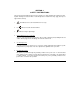


1. Mains In - Cord for delivering Mains Power(115V ac) to the instrument.
2. Output - Socket for plugging in the appliance / load to be monitored.There are 2 socets to share
the load of 20A equally.
3. Load Switch - Turns ON/OFF outgoing power to the load.Their are 2 switches for 2 output
sockets.
4. Fuse - Protective Fuse between mains & load.
5. RS232 Interface Connector - External PC communicates to the instrument using this
connector.
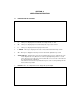
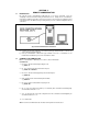
4.2 ELECTRICAL CONNECTIONS & MEASUREMENT
Follow the diagram & the instructions given below :
Fig. 3 Electrical connectons
a) Switch OFF the equipment under test.
b) Connect the Mains plug of the equipment/appliance, whose power is to be measured into
one of the Output sockets (2) of the 1523
c) With the corresponding load switch (3) of the 5051A in the ‘OFF’ position, Turn the mains
power on.
e) Switch ON the equipment/appliance & switch on the supply to the load with the
corresponding load switch(3).
Note : It is recommended that the 1523 be first switched ON and then the equipment under test.
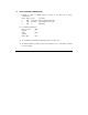
4.3 METER OPERATION
The ‘LCD display’ (7) on front panel shows the measured parameter selected. On power
‘ON’, the Manual Scan mode is chosen. In this mode parameter selected with front panel key
displayed constantly on display.
1. Note : If the user connects some load to the instrument & switches it on with help of load
switch(3) and if the current displayed by the instrument is 0.000A then it indicates a blown
fuse. User should replace it with a new fuse.