
Manual
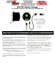

Exhaust Gas Temperature Gauge
For Product Numbers: MT-DV08, MT-DV08_1500, MT-WDV08, MT-
WDV08_1500
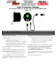
Wire Harness Color Code
Red:
12v Constant (un-switched) Source (+)
Black:
Vehicle / Engine Ground (-)
White:
12v Ignition (switched) Source (+)
Blue:
Connects to Black Wire on Sensor Harness
Orange:
12v Dimmer (switched) Source (+) (optional)
Pink:
Connects to White Wire on Sensor Harness
1. Disconnect the negative battery cable.
2. There are two common types of EGT probe installations. MaxTow
recommends installing the probe pre-turbo for the most accurate reading.
Exhaust Manifold: Drill and tap the exhaust manifold to
1/8
th
-27 NPT. Install the supplied EGT probe directly into your
exhaust manifold.
Note: After drilling and tapping your exhaust manifold be sure
to use both a magnet and vacuum to safely remove all shavings
from the manifold.
Exhaust Temperature Bracket: This method is not shown,
but you may purchase an exhaust temperature bracket from
www.MaxTow.com. This adapter is clamped and tightened
around the exhaust pipe and provides a 1/8
th
NPT fitting for an
EGT probe. Using a 3/16
th
drill bit, drill a hole in your exhaust
pipe. Position and tighten the adapter clamp, then permanently
mount the probe through the fitting and into the exhaust pipe.
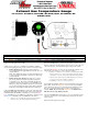
3. Route the EGT probe wire harness from the back of the gauge (slot
#2) through the firewall, engine bay and to the sensor. Next, couple and
secure the sensor wire harness to the EGT probe. Connect the pink
wire on the EGT probe to the white wire on the harness, and then connect
the blue wire on the EGT probe to the black wire on the harness.
Be sure to use a grommet when routing wires through the
firewall to protect them from stripping and damage.
4. Connect the white wire to a positive 12 volt ignition (switched) source.
It may be connected to the fuse panel, an accessory wire, or any positive 12
volt source that turns on and off with the ignition switch of the vehicle.
5. Connect the red wire to a positive 12 volt constant (un-switched) source,
either directly to the battery or to a fuse panel on the vehicle.
If wiring to an un-fused source, install a 3 amp fuse inline within
20 inches of the sources connection. You may obtain an optional
“expandable circuit” accessory. This component easily fits into
your fuse panel and provides an additional fused power wire for
accessories such as gauges. This is available at
www.MaxTow.com or a local auto parts store.
6. The Night Time Dimming feature decreases the brightness of the gauge
face by 30%. Connect the orange wire to the 12 volt positive headlamp
source. This allows the mode to be activated when the headlights come on.
This step is optional and will not affect operation of the gauge if it is
omitted. NOTE: Do not connect the orange wire to a dimmer wheel.
This will cause the gauge lighting to flicker.
7. Connect the black wire from the gauge, to any good (unpainted) ground
connection. You may also route a wire directly to the negative side of the
vehicle’s battery.
8. Reconnect the negative battery cable.