
GP-FLEX-30 - Product Manual


2
gpelectric.com
GP-FLEX-30
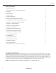
1.0 General Information 2
1.1 How Does a Go Power! Solar Charging Kit Work? 3
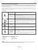
1.2 Warnings 3
1.3 Required Tools 3
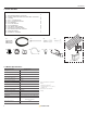
1.4 Parts Checklist 4
1.5 Module Specications 4
2.0 Wiring the Solar Module and Power Cable 5
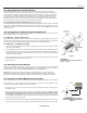
2.1 Installling your 30 watt Solar Flex
TM
Kit (GP-FLEX-30) 5
3.0 Routing Power Cable through the Fridge Vent 5
3.1 Method 1 – Hole in Side of Vent 5
3.2 Method 2 – Through Screen Grid 5
4.0 Mounting the Solar Module 6
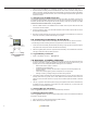
5.0 Installing The GP-PWM-10 Controller 6
5.1 Mounting The GP-PWM-10 Controller 6
6.0 Connecting to the Battery & Solar Array 6
6.1 Typical Battery Connection 7
7.0 Limited Warranty 7
7.1 General Warranty Issues 7
7.2 Warranty Return Procedure 7
7.3 Additional Information 7
7.4 Out of Warranty Items 7
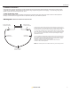
8.0 Diagram: MC4 Power Cabels For Solar Flex Kits 7
1.0 General Information
Congratulations on purchasing your Go Power!
Solar Flex
TM
Kit. You have chosen a clean, quiet and sustainable power source. Go Power!
Solar Charging Kits allow you to enjoy the luxuries that electricity provides, without hooking up to shore power, by keeping your batteries
charged. For simple battery maintenance to full-time live-aboard power, Go Power!
Solar Kits are available in a variety of sizes and can
be installed on RVs, boats, campers, trailers, fth wheels, motor homes, cottages/cabins, long-haul trucks and industrial applications. This
manual is geared towards RV installation. For other applications, please consult a certied electrician or contact Go Power! Technical Support.
Information in this manual is subject to change, please visit gpelectric.com for the most current version of this manual.
Table of Contents
Note: Solar Flex Modules have a 30° maximum recommended bend - 1.4” / 36mm bend (30 watt)