
GP-FLEX-30 - Product Manual


5
gpelectric.com
GP-FLEX-30
2.0 Wiring Modules with MC4 Cables
Solar Kits with MC4 cables contain a potted or sealed junction box with a positive and negative MC4
connector. This is referred to as an MC4 junction box. MC4 connectors are either positive or negative and
each connector has its polarity symbol embossed close to the connection point. To extend a cable from an
MC4 junction box, a polarity opposite connector must be used. E.G. a negative connector must plug into
a positive connector in order to extend it. Please remember, the polarity of an MC4 cable wire run is the
polarity symbol on the connector closest to the MC4 junction box. It is advisable to attach a polarity sticker
to the positive extension cable in order to avoid confusion during installation.
2.1 Installing your 30 watt Solar Flex
TM
Kit (GP-FLEX-30)
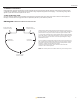
Solar Kits containing a single module with MC4 cables will be equipped with a single 50’ MC4 power cable
that has both a male and female MC4 connection. This cable is meant to be cut in half leaving you with a
25’ cable with a male MC4 and a 25’ cable with a female MC4 connection. Refer to Diagram-1, “MC4 Power
Cables for RV Kits.”
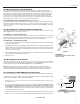
3.0 Routing Power Cable through the Fridge Vent
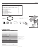
Locate the refrigerator vent on the roof of the RV. Remove vent cover to gain access to the duct opening.
Refer to Figure 1. Retain vent-fastening hardware.
3.1 Method 1 – Hole in Side of Vent
Drill a hole through the side of the vent (5/8” hole). Insert a rubber grommet (not included) into the hole. Insert
the power cable (already wired to the solar module) through the hole and carefully route it to the battery. Be
certain to leave enough slack to allow cable routing from module to vent along desired path.
3.2 Method 2 – Through Screen Grid
1. Thread power cable (already wired to solar module) carefully through the screen and into opening. Enlarge
screen grid hole if necessary.
2. Avoid strapping the power cable to existing wire between the module and the battery. Allowing a few inches
of space between the power cable and existing wire will lessen the chance of voltage loss through thermal
conduction. Use cable clamps with the #8 self-tapping screw and/or tie wraps every few feet along RV
roof and interior route to battery.
3. Ensure all penetrations into the RV roof are watertight. Use an appropriate sealant as recommended by
your RV Dealer to seal holes wherever necessary.
4. Replace vent cover.
4.0 Mounting the Solar Module
The solar modules may be horizontally mounted to the roof using the included screws or an adhesive
sealant. Please contact your RV manufacturer for specications on an appropriate adhesive. Panels are not
recommended to bend beyond 30° (for 30 watt modules 30° = 1.4” / 36mm bend )
Warning: Using an adhesive can create a permanent mounting situation. It is strongly advised that
placement is well thought out and that panel function has been tested before mounting. Go Power! and
Carmanah Technologies is not responsible for damage caused the by removal of Solar Flex
TM
Modules.
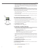
5.0 Installing The GP-PWM-10 Solar Controller
The 30 watt Solar Flex
TM
Kit includes a 10 amp Solar Controller, that protects the battery from overcharging.
A condensed version of the installation instructions appear below. Please read the full installation manual
included with the GP-PWM-10 Solar Controller before installing.
1. Disconnect or cover the solar modules and disconnect the batteries before commencing the
GP-PWM-10 wiring.
2. Run the solar module power cable to the location of The GP-PWM-10. Do not connect the wires to
the controller or the batteries. Identify the polarity of the wires located on the battery and solar
module (positive and negative). Use coloured tape or mark wire ends with tags. Contacting the leads
of the controller in reverse polarity, however brief, will cause the controller to go into lock out mode and
the solar controller will need to be reset.
3. Kits include a fuse holder with an inline 10A fuse to protect the wire between the battery and solar controller.
Install your inline fuse as close to the battery as possible before connecting the solar controller to the
Caution:
The vent screen may have sharp
edges or burrs.
Figure 1
Vent
Screen
Refrigerator
Vent Cover
Solar
Module
Cable
Clamps
Method 2
Method 1
Fuse
Positive
Connection
Negative
Connection
12 Volt Battery Connected to
Solar Controller with Inline Fuse
Figure 2
Solar
Controller