
GP-FLEX-30 - Product Manual


6
gpelectric.com
GP-FLEX-30
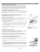
battery terminal. See Figure 2: “12 Volt Battery Connected to Solar Controller with Inline Fuse”.
4. Wire the controller according to the terminal identication on the back of controller, starting with the
battery connections. Tighten the positive and negative battery connections and then set the battery
type (see controller manual for instruction). Then, connect and tighten the positive and negative solar
module connections.
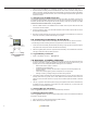
5.1 Mounting The GP-PWM-10 Controller
The GP-PWM-10 should be mounted in a location as close to the battery as possible, but easily seen
for monitoring system operation. Wires must be run from the solar module to the controller and then to
the battery. The GP-PWM-10 is designed to be mounted vertically, on the side of a cabinet or wall. The
controller should be mounted indoors, in a dry location.
1. Select a suitable location for the installation of the controller. Run the power cable from the solar
module to the location selected.
2. Wire the controller as shown in the GP-PWM-10 Manual. Use the leftover power cable to connect
the controller to the batteries.
3. Mount the controller to the wall using the two screws provided in the GP-PWM-10 box. Ensure the
back of the controller is protected from damage by any object.
6.0 Connecting to the Battery & Solar Array
It is recommended to connect directly to the battery wherever possible. You can also connect to the
converter/charger where the battery positive and negative wires connect to the converter.
1. Clean all corrosion from battery terminals before proceeding. Crimp ring terminals onto the negative
and positive wires of the power cable to be attached to the battery.
2. Attach the negative (black) wire’s 3/8” ring terminal to the RV battery. Check all electrical connections
and apply a protective coating to battery terminals.
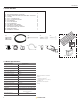
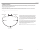
6.1 Typical Battery Connection
1. Single 12 Volt battery connection (See Figure 3)
7.0 Disclaimer of Liability & Warranty
1. Go Power! warrants the Solar Flex
TM
Kit for a period of one (1) year from the date of shipment from
its factory. This warranty is valid against defects in materials and workmanship for the one (1) year
warranty period. It is not valid against defects resulting from, but not limited to:
• Misuse and/or abuse, neglect, or accident
• Exceeding the unit’s design limits
• Improper installation, including, but not limited to, improper environmental protection and
improper hook-up
• Acts of God, including lightning, oods, earthquakes, re, and high winds
• Damage in handling, including damage encountered during shipment
2. This warranty shall be considered void if the warranted product is in any way opened or altered. The
warranty will be void if any eyelet, rivets, or other fasteners used to seal the unit are removed or
altered, or if the unit’s serial number is in any way removed, altered, replaced, defaced or rendered
illegible.
3. The one (1) year term of this warranty does not apply to equipment where another limited warranty
is available. This may include but is not limited to, the solar controller one (1) year and the solar
module ten (10) years (output warranty).
7.1 General Warranty Informtaion
Please visit gpelectric.com for our up-to-date General Warranty Information
7.2 Warranty Return Procedure
Please visit gpelectric.com to read the “frequently asked questions” section of our website to troubleshoot
the problem. If trouble persists:
1. Call your Go Power!™ Technical Support team (1-866-247-6527)
2. Return defective product to place of purchase
Figure 3
Single 12 Volt Battery
12 Volt Conguration
Solar
Controller
Negative
Connection
Positive
Connection