
GP-FLEX-30 - Product Manual


7
gpelectric.com
GP-FLEX-30
7.3 Additional Information
Unless approved by Go Power! management, all product shipped collect to Go Power! will be refused. Test items or items that are not under warranty,
or units that are not defective, will be charged a minimum bench charge of ($50.00 US) plus taxes and shipping. A 15% restocking charge will be
applied on goods returned and accepted as “new” stock.
7.4 Out of Warranty Items
Go Power! electronic products are non-repairable, Go Power!
does not perform repairs on its products nor does it contract out those repairs to a
third party. Go Power!
does not supply schematics or replacement parts for any of its electronic products.
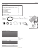
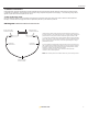
8.0 Diagram:
MC4 Power Cabels For Solar Flex Kits
The MC4 power cable is usually the nal connection between the solar array and
the solar controller. If it has not already been done, cut the MC power cable into two
pieces so that there is a positive conductor cable and negative conductor cable.
1. Cover the solar module(s) with an opaque material. Attach the appropriate MC4
power cable conductor to the positive and negative connectors of the MC4 junction
box. If you have more than one module, refer to the specic diagram for wiring a
parallel MC4 connection.
2. Run the positive and negative MC4 cable conductors from the solar array to the
solar controller. Attach a positive polarity label to the end of the positive conductor.
If the positive conductor needs to be shortened and the polarity label is removed,
remember to re-label it as both positive and negative
conductors look exactly the same. Leave a few feet of cable at the solar
controller in case of future adjustment.
Note: solar module junction box and MC4 cables many not be exactly as shown.
Negative MC4
Cable Conductor
Positive MC4
Cable Conductor
Cut 50’ wire in half to
make two 25’ cables
Female (negative) MC4
Junction Box Connection
Male (positive) MC4
Junction Box Connection