
Manual


24
*
*
*
**
*
*
*
*
STANDARD
JUNCTION BOX
LOCATION
ALTERNATE
JUNCTION BO
X
LOCATION
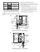
Junction Box Relocation
HIGH VOLTAGE!
T
O
AVOID
THE
RISK
OF
INJURY
,
ELECTRICAL
SHOCK
OR
DEATH
,
THE
FURNACE
MUST
BE
ELECTRICALLY
GROUNDED
IN
ACCORDANCE
WITH
LOCAL
CODES
OR
IN
THEIR
ABSENCE
,
WITH
THE
LATEST
EDITION
OF
THE
N
ATIONAL
E
LECTRIC
C
ODE
.
WARNING
To ensure proper unit grounding, the ground wire should run from
the furnace ground screw located inside the furnace junction box
all the way back to the electrical panel. NOTE: Do not use gas
piping as an electrical ground. To confirm proper unit grounding,
turn off the electrical power and perform the following check.
1. Measure resistance between the neutral (white) connection
and one of the burners.
2. Resistance should measure 10 ohms or less.
This furnace is equipped with a blower door interlock switch which
interrupts unit voltage when the blower door is opened for servic-
ing. Do not defeat this switch.
24 VOLT THERMOSTAT W IRING
NOTE: Wire routing must not interfere with circulator blower
operation, filter removal, or routine maintenance.
Low voltage connections can be made through either the right or
left side panel. Thermostat wiring entrance holes are located adja-
cent to the junction box locations in the blower compartment. Wire
routing must not to interfere with circulator blower operation, filter
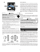
removal, or routine maintenance. Refer to the following figure for
thermostat connections to the integrated control module terminal
strip.
W
W
W
Y
Y
Y
C
C
R
R
R
G
G
W
Y
C
R
G
HEATI NG
ROOM
THERMOSTAT
HEATING AND
COOLING ROOM
THERMOSTAT
FURNACE
FURNACE
REMOTE
CONDENSI N
G
UNI T
Thermostat Diagram
This furnace is equipped with a 40 VA transformer to facilitate use
with most cooling equipment. Consult the wiring diagram, located
on the blower compartment door, for further details of 115 Volt and
24 Volt wiring.
24 VOLT HUMIDIFIER
The yellow wire connected to the I.D. Blower pressure switch is
powered anytime the pressure switch is closed and provides 24
VAC humidifier control. Remove the yellow wire and connect a field
supplied jumper wire with a “piggyback” terminal to the pressure
switch terminal. Reconnect the yellow wire to the “piggyback” ter-
minal on the jumper wire and then connect the 24 VAC line of the
humidifier to the stripped end of the jumper wire. Using a wire nut
or a field-supplied quick connect terminal can make this connec-
tion. The wiring must conform to all local and national codes. Con-
nect the COM side of the humidifier to the B/C terminal on the
furnace control board (or to the COM side of the 24 VAC trans-
former). DO NOT CONNECT 115V HUMIDIFIER TO THESE TERMI-
NALS.
XII. GAS SUPPLY AND PIPING
GENERAL
The furnace rating plate includes the approved furnace gas input
rating and gas types. The furnace must be equipped to operate on
the type of gas applied. This includes any conversion kits required
for alternate fuels and/or high altitude.
T
O
PREVENT
UNRELIABLE
OPERATION
OR
EQUIPMENT
DAMAGE
,
THE
GAS
MANIFOLD
PRESSURE
MUST
BE
AS
SPECIFIED
ON
THE
UNIT
RATING
PLATE
. O
NLY
MINOR
ADJUSTMENTS
SHOULD
BE
MADE
BY
ADJUSTING
THE
GAS
VALVE
PRESSURE
REGULATOR
.
CAUTION
Inlet gas supply pressures must be maintained within the ranges
specified below. The supply pressure must be constant and avail-
able with all other household gas fired appliances operating. The
minimum gas supply pressure must be maintained to prevent
unreliable ignition. The maximum must not be exceeded to pre-
vent unit overfiring.
Natural Gas Minimum: 4.5" W.C. Maximum: 10.0" W.C.
Propane Gas Minimum: 11.0" W.C. Maximum: 13.0" W.C.
Inlet Gas Supply Pressure
HIGH ALTITUDE DERATE
When this furnace is installed at high altitude, the appropriate High
Altitude orifice kit must be applied. This is required due to the
natural reduction in the density of both the gas fuel and combus-
tion air as altitude increases. The kit will provide the proper design
certified input rate within the specified altitude range.
High altitude kits are purchased according to the installation alti-
tude and usage of either natural or propane gas. Contact your
distributor for a tabular listing of appropriate altitude ranges and
corresponding manufacturer’s high altitude (Natural, Propane Gas,
and/or Pressure Switch) kits.
Do not derate the furnace by adjusting the manifold pressure to a
lower pressure than specified on the furnace rating plate. The
combination of the lower air density and a lower manifold pressure
will prohibit the burner orifice from drawing the proper amount of
air into the burner. This may cause incomplete combustion, flash-
back, and possible yellow tipping.
In some areas the gas supplier may artificially derate the gas in an
effort to compensate for the effects of altitude. If the gas is artifi-
cially derated, the appropriate orifice size must be determined
based upon the BTU/ft
3
content of the derated gas and the altitude.