
Manual


29
Refer to Minimum Filter Area tables to determine filter area require-
ments.
600 800 1000 1200 1400 1600 2000
0453_XA 188* 192 240 288 --- --- ---
0703_XA --- 282* 282* 282* 336 --- ---
0704_XA --- --- 260* 260* 336 384 ---
0904_XA --- --- 376* 376* 376* 384 ---
0905_XA --- --- --- 376* 376* 384 480
115_XA --- --- --- 470* 470* 470* 480
Input__Airflow
COOLING AIRFLOW REQUIREMENT (CFM)
*Minimum filter area dictated by heating airflow requirement.
Permanent Minimum Filter Area (sq. in)
[Based on a 600 ft/min filter face velocity]
600 800 1000 1200 1400 1600 2000
0453_XA 376* 384 480 576 --- --- ---
0703_XA --- 564* 564* 564* 672 --- ---
0704_XA --- --- 564* 564* 672 768 ---
0904_XA --- --- 752* 752* 752* 768 ---
0905_XA --- --- --- 752* 752* 768 800
1155_XA --- --- --- 940* 940* 940* 800
Input__Airflow
COOLING AIRFLOW REQUIREMENT (CFM)
*Minimum filter area dictated by heating airflow requirement.
Disposable Minimum Filter area (sq. in)
[Based on 300 ft/min filter face velocity]
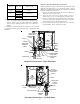
UPRIGHT INSTALLATIONS
Depending on the installation and/or customer preference, differ-
ing filter arrangements can be applied. Filters can be installed in
the central return register or a side panel external filter rack kit
(upflows). As an alternative a media air filter or electronic air cleaner
can be used as the requested filter.
The following figure shows possible filter locations.
FILTER
AIR FLOW
CENTRAL
RETURN
GRILLE
FILTER
SIDE RETURN
EXTERNAL FILTER
RACK KIT
(EITHER SIDE)
Possible Upright Upflow
Filter Locations
HORIZONTAL I NSTALLATIONS
Filters must be installed in either the central return register or in the
return air duct work.
XIV. STARTUP PROCEDURE & ADJUSTMENT
Furnace must have a 115 VAC power supply properly connected
and grounded. Proper polarity must be maintained for correct op-
eration. In addition to the following start-up and adjustment items,
refer to further information in Section XVI, Operational Checks.
HEAT ANTICIPATOR S ETTING
The heat anticipator in the room thermostat must be correctly ad-
justed to obtain the proper number of cycles per hour and to pre-
vent “overshooting” of the setting. Set the heat anticipator setting to
0.7 amps. Follow the thermostat manufacturer’s instructions on
how to adjust the heat anticipator setting.
DRAIN TRAP PRIMING
The drain trap must be primed prior to furnace startup. To prime, fill
the drain trap with water. This ensures proper furnace drainage
upon startup and prohibits the possibility of flue gases escaping
through the drain system.
FURNACE OPERATION
Purge gas lines of air prior to startup. Be sure not purge lines into
an enclosed burner compartment.
Check for leaks using an approved chloride-free soap and water
solution, an electronic combustible gas detector, or other approved
method. Verify that all required kits (propane gas, high altitude,
etc.) have been appropriately installed.
FURNACE STARTUP
1. Close the manual gas shutoff valve external to the furnace.
2. Turn off the electrical power to the furnace.
3. Set the room thermostat to the lowest possible setting.
4. Remove the burner compartment door.
NOTE: This furnace is equipped with an ignition device which
automatically lights the burner. Do not try to light the burner by
hand.
5. Move the furnace gas valve manual control to the OFF
position.
6. Wait five minutes then smell for gas. Be sure to check near
the floor as some types of gas are heavier than air.
7. If you smell gas after five minutes, immediately follow the
instructions on page 4 of this manual. If you do not smell
gas after five minutes, move the furnace gas valve manual
control to the ON position.
8. Replace the burner compartment door.
9. Open the manual gas shutoff valve external to the furnace.
10. Turn on the electrical power to the furnace.
11. Adjust the thermostat to a setting above room temperature.
12. After the burners are lit, set the thermostat to desired
temperature.
FURNACE SHUTDOWN
1. Set the thermostat to the lowest setting.
The integrated control will close the gas valve and extinguish
flame. Following a 15 second delay, the induced draft blower
will be de-energized. After a 150-second delay period (fixed),
the circulator blower will be de-energized.