
Manual


32
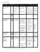
RISE =
SUPPLY
AIR
RETURN
AIR
HEAT EXCHANGER
RADIATION "LINE OF SIGHT"
T
RETURN
T
SUPPLY
T
SUPPLY
-
T
RETURN
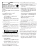
Temperature Rise Measurement
3. Subtract the return air temperature from the supply air
temperature to determine the air temperature rise. Allow
adequate time for thermometer readings to stabilize.
4. Adjust temperature rise by adjusting the circulator blower
speed. Increase blower speed to reduce temperature rise.
Decrease blower speed to increase temperature rise. Refer
to Section XIV, Startup Procedure and Adjustment -Circulator
Blower Speeds for speed changing details.
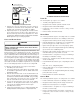
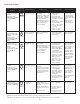
CIRCULATOR B LOWER SPEEDS
T
O
PREVENT
PREMATURE
FAILURE
OF
HEAT
EXCHANGER
,
PROPERTY
DAMAGE
,
PERSONAL
INJURY
OR
DEATH
,
DO
NOT
ADJUST
THE
LIMIT
CONTROL
(
FACTORY
-
SET
).
WARNING
This furnace is equipped with a multi-speed circulator blower. This
blower provides ease in adjusting blower speeds. The Specifica-
tion Sheet applicable to your model provides an airflow table, show-
ing the relationship between airflow (CFM) and external static pres-
sure (E.S.P.), for the proper selection of heating and cooling speeds.
The cooling blower speed is shipped set on HIGH, and the heating
blower speed is set as indicated in the Specification Sheet appli-
cable to your model. These blower speeds should be adjusted by
the installer to match the installation requirements so as to provide
the correct heating temperature rise and correct cooling CFM.
To adjust the circulator blower speed, proceed as follows:
1. Turn OFF power to the furnace.
2. Select the heating and cooling blower speeds that match
the installation requirements from the airflow table in the
Specification Sheet.
3. Relocate desired motor leads to the circulator blower heat
and cool speed terminals on the integrated control module.
(Terminals are identified as HEAT and COOL (hot)). If heating
and cooling blower speeds are the same, a jumper wire
must be used between the heat and cool terminals.
4. Connect all unused blower motor leads to the “PARK”
terminals on the integrated control module. Any leads not
connected to the “PARK” terminals must be taped.
5. Turn ON power to furnace.
6. Verify proper temperature rise as outlined in Section XIV,
Startup Procedure and Adjustment - Temperature Rise.
Oran
g
e
Hi
g
h
Common/Neutral
Medium Low
Circulator Blower S
p
eeds
Low Red
Medium Blue
Black
White
XV. NORMAL SEQUENCE OF OPERATION
POWER UP
The normal power up sequence is as follows:
• 115 VAC power applied to furnace.
• Integrated control module performs internal checks.
• Integrated control module LED will light.
• Integrated control module monitors safety circuits
continuously.
• Furnace awaits call from thermostat.
HEATING MODE
The normal operational sequence in heating mode is as follows:
• R and W thermostat contacts close, initiating a call for heat.
• Integrated control module performs safety circuit checks.
• Induced draft blower is energized for 15 second prepurge
period causing pressure switch contacts to close.
• Igniter warm up begins after 15 second prepurge expires.
• Gas valve opens at end of igniter warm up period, delivering
gas to burners and establishing flame.
• Integrated control module monitors flame presence. Gas
valve will remain open only if flame is sensed.
• Circulator blower is energized on heat speed following a
fixed thirty second blower on delay.
• Furnace runs, integrated control module monitors safety
circuits continuously.
• R and W thermostat contacts open, completing the call for
heat.
• Gas valve closes, extinguishing flame.
• Induced draft blower is de-energized following a fifteen
second post purge.
• Circulator blower is de-energized following the heat off delay
period (fixed 150 seconds).
• Furnace awaits next call from thermostat.
COOLING MODE
The normal operational sequence in cooling mode is as follows:
• R and Y thermostat contacts close, initiating a call for cool.
• Integrated control module performs safety circuit checks.
• Outdoor fan and compressor are energized.
• Circulator blower is energized on cool speed following a
fixed five second on delay.
• Furnace circulator blower and outdoor cooling unit run,
integrated control module monitors safety circuits
continuously.