
Manual


33
• R and Y thermostat contacts open, completing the call for
cool.
• Outdoor fan and compressor are de-energized.
• Circulator blower is de-energized following a fixed forty five
second cool off delay period.
• Furnace awaits next call from thermostat.
FAN ONLY MODE
The normal operational sequence in fan only mode is as follows:
• R and G thermostat contacts close, initiating a call for fan.
• Integrated control module performs safety circuit checks.
• Circulator blower is energized on heat speed.
• Circulator blower runs, integrated control module monitors
safety circuits continuously.
• R and G thermostat contacts open, completing the call for
fan.
• Circulator blower is de-energized.
• Furnace awaits next call from thermostat.
XVI. OPERATIONAL CHECKS
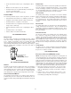
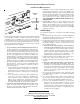
BURNER FLAME
The burner flames should be inspected with the burner compart-
ment door installed. A sight glass is provided for inspection pur-
poses. Flames should stable, quiet, soft, and blue (dust may
cause orange tips but they must not be yellow). Flames should
extend directly outward from the burners without curling, floating, or
lifting off. Flames must not impinge on the sides of the heat ex-
changer firing tubes.
Check the burner flames for:
1. Good adjustment
2. Stable, soft and blue
3. Not curling, floating, or lifting off.
Burner Flame
XVII. SAFETY CIRCUIT DESCRIPTION
GENERAL
A number of safety circuits are employed to ensure safe and proper
furnace operation. These circuits serve to control any potential
safety hazards and serve as inputs in the monitoring and diagno-
sis of abnormal function. These circuits are continuously moni-
tored during furnace operation by the integrated control module.
INTEGRATED C ONTROL MODULE
The integrated control module is an electronic device which, if a
potential safety concern is detected, the module will take the nec-
essary precautions and provide diagnostic information through an
LED.
PRIMARY LIMIT
The primary limit control is located on the partition panel and moni-
tors heat exchanger compartment temperatures. It is a normally-
closed (electrically), automatic reset, temperature-activated sen-
sor. The limit guards against the overheating as a result of insuffi-
cient conditioned air passing over the heat exchanger.
AUXILIARY L IMIT
The auxiliary limit control(s) are located on or near the circulator
blower and monitors heat exchanger compartment temperatures.
They are a normally-closed (electrically), manual-reset, tempera-
ture activated sensors. These limits guard against overheating as
a result of insufficient conditioned air passing over the heat ex-
changer.
ROLLOUT L IMIT
The rollout limit controls are mounted on the burner/manifold as-
sembly and monitor the burner flame. They are normally-closed
(electrically), manual-reset, temperature-activated sensors. These
limits guard against burner flames not being properly drawn into
the heat exchanger.
PRESSURE S WITCHES
The pressure switches are normally-open (closed during opera-
tion), single-pole single-throw, negative air pressure-activated
switches. They monitor the airflow (combustion air and flue prod-
ucts) through the heat exchanger via pressure taps located on the
induced draft blower and the coil front cover. These switches guard
against insufficient airflow (combustion air and flue products)
through the heat exchanger and/or blocked condensate drain con-
ditions.
FLAME SENSOR
The flame sensor is a probe mounted to the burner/manifold as-
sembly which uses the principle of flame rectification to determine
the presence or absence of flame.
XVIII. TROUBLESHOOTING
ELECTROSTATIC D ISCHARGE (ESD) PRECAUTIONS
NOTE: Discharge body’s static electricity before touching unit. An
electrostatic discharge can adversely affect electrical components.
Use the following precautions during furnace installation and ser-
vicing to protect the integrated control module from damage. By
putting the furnace, the control, and the person at the same electro-
static potential, these steps will help avoid exposing the integrated
control module to electrostatic discharge. This procedure is appli-
cable to both installed and uninstalled (ungrounded) furnaces.
1. Disconnect all power to the furnace. Do not touch the
integrated control module or any wire connected to the control
prior to discharging your body’s electrostatic charge to
ground.
2. Firmly touch a clean, unpainted, metal surface of the
furnaces near the control. Any tools held in a person’s
hand during grounding will be discharged.