*MH95/ACSH96/AMEH96/ GCH95/GME95/GCH9 GAS-FIRED WARM AIR FURNACE INSTALLATION INSTRUCTIONS Installer: Affix all manuals adjacent to the unit. (Type FSP CATEGORY IV Direct or Non Direct Vent Air Furnace) These furnaces comply with requirements embodied in the American National Standard / National Standard of Canada ANSI Z21.47·CSA-2.3 Gas Fired Central Furnaces. RECOGNIZE THIS SYMBOL AS A SAFETY PRECAUTION.
Table of Contents I. Component Identification ................................................................................................................................................ 5 II. Safety Considerations .................................................................................................................................................... 6 ELECTROSTATIC DISCHARGE (ESD) PRECAUTIONS ..................................................................................................
Table of Contents XIV. Startup Procedure & Adjustment ............................................................................................................................. 33 HEAT ANTICIPATOR SETTING .............................................................................................................................. 33 DRAIN TRAP PRIMING .......................................................................................................................................
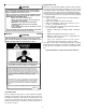
SHIPPING INSPECTION WARNING All units are securely packed in shipping containers tested according to International Safe Transit Association specifications. The carton must be checked upon arrival for external damage. If damage is found, a request for inspection by carrier’s agent must be made in writing immediately. The furnace must be carefully inspected on arrival for damage and bolts or screws which may have come loose in transit. In the event of damage the consignee should: 1.
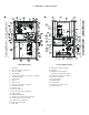
I.
II. SAFETY CONSIDERATIONS WARNING Adhere to the following warnings and cautions when installing, adjusting, altering, servicing, or operating the furnace. To ensure proper installation and operation, thoroughly read this manual for specifics pertaining to the installation and application of this product. This furnace is manufactured for use with natural gas. It may be field converted to operate on L.P. gas by using the appropriate L.P.
• It must be installed with two-pipe systems for combustion air, especially if VOC’s or other contaminants are present in the conditioned space. SHOULD OVERHEATING OCCUR OR THE GAS SUPPLY FAIL TO SHUT OFF, • All other warranty exclusions and restrictions apply This TURN OFF THE MANUAL GAS SHUTOFF VALVE EXTERNAL TO THE furnace is an ETL dual-certified appliance and is FURNACE BEFORE TURNING OFF THE ELECTRICAL SUPPLY.
• WARNING POSSIBLE PROPERTY DAMAGE, PERSONAL INJURY OR DEATH DUE TO FIRE, EXPLOSION, SMOKE, SOOT, CONDENSATION, ELECTRICAL SHOCK OR CARBON MONOXIDE MAY RESULT FROM IMPROPER INSTALLATION, REPAIR, OPERATION, OR MAINTENANCE OF THIS PRODUCT . WARNING • TO PREVENT PERSONAL INJURY, PROPERTY DAMAGE OR DEATH DUE TO FIRE, DO NOT INSTALL THIS FURNACE IN A MOBILE HOME, TRAILER OR RECREATIONAL VEHICLE.
• • • • Seal off a non-direct vent furnace if it is installed near an area frequently contaminated by any of the above substances. This protects the non-direct vent furnace from airborne contaminants. To ensure that the enclosed non-direct vent furnace has an adequate supply of combustion air, vent from a nearby uncontaminated room or from outdoors. Refer to the Combustion and Ventilation Air Requirements for details.
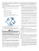
If resizing is required on any portion of the venting system, use the appropriate table in Appendix G in the latest edition of the National Fuel Gas Code ANSI Z223.1 and/or CSA B149.1-05.1-05 Installation Codes. THERMOSTAT LOCATION The thermostat should be placed approximately five feet from the floor on a vibration-free, inside wall in an area having good air circulation.
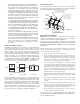
Chimney or Gas Vent Chimney or Gas Vent NOTE: Each opening must have a free area of not less than one square inch per 1000 BTU of the total input rating of all equipment in the enclosure, but not less than 100 square inches. Ventilation louvers (each end of attic) NOTE: The inlet and outlet air openings must each have a free area of not less than one square inch per 4000 BTU of the total input rating of all equipment in the enclosure.
5. When directly communicating with the outdoors, the single opening shall have a minimum free area of 1 square inch per 3,000 BTU per hour of total input rating of all equipment in the enclosure. LOCATION 5.3.4 Specially Engineered Installations: The requirements of 5.3.3 shall not necessarily govern when special engineering, approved by the authority having jurisdiction, provides an adequate supply of air for combustion, ventilation, and dilution of flue gases. 5.3.
AIR DISCHARGE Bottom Return Duct Connection ALTERNATE FLUE PIPE LOCATION Side Return Duct Connection VIII.
V X v DIRECT VENT TERMINAL CLEARANCES Canadian Installations 1 U.S. Installations 2 A= Clearance above grade, veranda, porch, deck or balcony. (See 1.24.6-i(9)b.) 12 in. (30 cm) 12 in. (30 cm) B= Clearance to window or door that may be opened. 6 in. (15 cm) for appliances 10,000 Btuh (3 kW), 12 in. (30 cm) for appliances > 10,000 Btuh (3 kW) and 100,000 Btuh (30 kW), 36 in. (91 cm) for appliances > 100,000 Btuh (30 kW). 6 in. (15 cm) for appliances 10,000 Btuh (3 kW), 9 in.
tic pipe is also acceptable as a flue/vent and intake pipe material. PVC primer meeting ASTM F656 and PVC solvent cement meeting ASTM D2564 specifications must be used. Fittings must be DWV type fittings meeting ASTM D2665 and ASTM D3311. Carefully follow the manufactures instructions for cutting, cleaning and solvent cementing of PVC. IX. VENT/FLUE PIPE & COMBUSTION AIR PIPE GENERAL WARNING FAILURE TO FOLLOW THESE INSTRUCTIONS CAN RESULT IN BODILY INJURY OR DEATH.
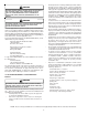
VENT/FLUE PIPE TERMINATION LOCATIONS NOTES: Refer to Location Requirements and Considerations for combustion air contaminant restrictions. The following bullets and diagram describe the restrictions concerning the appropriate location of vent/flue pipe and combustion air intake pipe (when applicable) terminations. Refer to Non-Direct Vent (Single Pipe) Piping and Direct Vent (Dual Pipe) Piping located in this section for specific details on termination construction.
COMBUSTION AIR PIPE (DIRECT VENT ONLY) COMBUSTION AIR PIPE (DIRECT VENT ONLY) VENT/FLUE PIPE VENT/FLUE PIPE FLANGE 3.75" 90º PVC ELBOW (NON-DIRECT VENT) RUBBER COUPLING WITH WORM GEAR CLAMPS 90º PVC ELBOW (NON-DIRECT VENT) RUBBER COUPLINGS WITH WORM GEAR CLAMPS CUT HERE OR OR UPFLOW Vent/Flue Pipe Cuts 5. Remove plastic plug from alternate vent/flue location. Relocate and install plug in standard vent/flue location (top cover). Counterflow units.
*MH95/ACSH96/AMEH96/GCH95/GME95 5 ADDITIONAL PLUG FROM DRAIN KIT Direct Vent (2 - Pipe) and Non-Direct Ve nt (1- Pipe) (6) Maximum Allowable Length of Vent/Flue Pipe & Combustion Air Pipe (ft) 7 EXTERNALLY MOUNT RUBBER ELBOW Unit Input (Btu) 6 SECURE TO ID BLOWER WITH RUBBER COUPLING AND HOSE CLAMPS 40,000 45,000 60,000 COUNTERFLOW/UPRIGHT (UPFLOW SIMILAR) 6 SECURE TO ID BLOWER WITH RUBBER COUPLING AND HOSE CLAMPS 70,000 80,000 6 SECURE TO CABINET WITH SCREWS UPFLOW/HORIZONTAL (COUNTERFLOW SIMILA
VENT/FLUE TEE (OPTIONAL) COMBUSTION AIR INTAKE (OPTIONAL) 12” MIN HEIGHT DIFFERENCE BETWEEN INTAKE AND VENT *Not required for single pipe installation O RO FL INE INTAKE SCREEN OPTIONAL . AX ”M 6 9 AND COMBUSTION AIR PIPE LENGTHS AND DIAMETERS Refer to the following table for applicable length, elbows, and pipe diameter for construction of the vent/flue and combustion air intake pipe systems of a direct vent (dual pipe) installation.
90° ELBOWS 3” - 24” 3” - 24” 12” MIN SEPARATION 3” MIN AIR INTAKE SCREEN (OPTIONAL) OPTIONAL INTAKE SCREENS 12" MIN. ABOVE HIGHEST ANTICIPATED SNOW LEVEL 12” MIN TO GRADE OR HIGHEST ANTICIPATED SNOW LEVEL Termination of Multiple Direct Vent Furnaces Alternate Horizontal Vent Termination (Dual Pipe) CONCENTRIC VENT TERMINATION Refer to the directions provided with the Concentric Vent Kit (DCVK) for installation specifications.
• If an air conditioning coil is installed with the furnace, a common drain may be used. An open tee must be installed in the drain line, near the cooling coil, to relieve positive air pressure from the coil’s plenum. This is necessary to prohibit any interference with the function of the furnace’s drain trap. In a upright installation drain hoses are connected to drain ports on the rubber elbow and the recuperator coil front cover.
ALTERNATE VENT/FLUE DRAIN HOSE CONNECTIONS Upright installations using the alternate vent/flue outlet will require “right-side only” drain hoses to be connected as follows. Refer to Vent/Flue Pipe and Combustion Air Pipe for details on alternate vent/flue pipe connection. 1. Remove the rubber plug from the right-side drain port on the front cover . Save for use in step 3. 2. Secure Hose A to front cover drain port with a red hose clamp. Route hose to rear right side panel grommet hole. 3.
4. Insert Tube 1 into rubber elbow drain port and secure with silver hose clamp. Angle tube outward toward front of furnace. 5. Cut “X” inches from the long end of Hose B and discard. Refer to table for appropriate length to cut. Secure remaining hose to Tube 1 with a green hose clamp. Route other end of Hose B to front left side panel grommet hole.
Cabinet Width (inches) Models (kBTU_Tons) "X" Length to Cut From Long End of Hose B (inches) 17 1/2 040_3, 045_30, 060_3 7 21 070_40, 080_5 3 1/2 24 1/2 090_50, 100_5 115_50 None UPRIGHT DRAIN TRAP MOUNTING (LEFT OR RIGHT SIDE PANEL) 1. Insert drain tubes into drain trap and position the drain trap against the side panel. NOTE: Drain tubes must reach the bottom of the drain trap. 2.
4. Remove the rubber cap from the side drain port on the rubber elbow. Horizontal installations with the left side panel down will require 5. Secure the short end of Hose B to rubber elbow side drain drain hoses to be connected to the left side front cover drain port port using a green hose clamp. NOTE: For left side drainage, and the side drain port on the rubber elbow. route hose to far left (down) side panel grommet holes. NOTE: Horizontal left side connections (when using new 1.
Line voltage connections can be made through either the right or left side panel. The furnace is shipped configured for a left side (right side for counterflows) electrical connection with the junction box located inside the burner compartment. To make electrical connections through the opposite side of the furnace, the junction box must be relocated to the other side of the burner compartment prior to making electrical connections. To relocate the junction box, observe the following steps. XI.
24 VOLT THERMOSTAT WIRING NOTE: Wire routing must not interfere with circulator blower operation, filter removal, or routine maintenance. ECO-TECH MOTOR Y W W Y W G R G R C HEATING ROOM THERMOSTAT FURNACE W Hi-Heat Cool Lo-Heat T2 Field Supplied Relay Y Y R R Furnace Control T4 Line-H T5 T3 Low voltage connections can be made through either the right or left side panel. Thermostat wiring entrance holes are located in the blower compartment.
If it is necessary for the installer to supply additional line voltage wiring to the inside of the furnace, the wiring must conform to all local codes, and have a minimum temperature rating of 105°C. All line voltage wire splices must be made inside the furnace junction box. The integrated control module electronic air cleaner terminals (EAC) are energized with 115 volts whenever the circulator blower is energized.
Natural Gas Capacity of Pipe In Cubic Feet of Gas Per Hour (CFH) Length of Nominal Black Pipe Size Pipe in Feet 1/2" 3/4" 1" 1 1/4" 10 132 278 520 1050 20 92 190 350 730 30 73 152 285 590 40 63 130 245 500 50 56 115 215 440 60 50 105 195 400 70 46 96 180 370 80 43 90 170 350 90 40 84 160 320 100 38 79 150 305 (Pressure 0.5 psig or less and pressure drop of 0.3" W.C.; Based on 0.60 Specific Gravity Gas) rigid pipe must be used to reach the outside of the cabinet.
Gas Piping Connections MANUAL SHUT-OFF VALVE (UPSTREAM FROM GROUND JOINT PIPE UNION) GROUND JOINT PIPE UNION ALTERNATE UNION LOCATION WARNING DRIP LEG EDGES OF SHEET METAL HOLES MAY BE SHARP. USE GLOVES AS A PRECAUTION WHEN REMOVING HOLE PLUGS.
PROPANE GAS TANKS AND PIPING Sizing Between Single or Second Stage Regulator and Appliance* Maximum Propane Capacities Listed are Based on 1/2" W.C. pressure drop at 11" W.C. setting. Capacities in 1,000 BTU/hour. Pipe or Nominal Pipe Size Tubing Tubing Size, O.D.
CHECKING DUCT STATIC BOTTOM RETURN AIR OPENING [UPFLOW MODELS] Refer to your furnace rating plate for the maximum ESP (external duct static) rating. Total external static refers to everything external to the furnace cabinet. Cooling coils, filters, ducts, grilles, registers must all be considered when reading your total external static pressure. The supply duct pressure must be read between the furnace and the cooling coil.
1600 2000 040_3BXA 0453BXA 194* 194* 240 288 --- --- --- 060_3BXA 0703BXA --- 324* 324* 324* 336 --- --- 0704CXA --- --- 291* 291* 336 384 --- 0904CXA --- --- 432* 432* 432* 432* --- 080_5CXA 0905DXA --- --- --- 388* 388* 388* 480 100_5DXA 1155DXA --- --- --- 486* 486* 486* 486* FILTER ACCESS DOOR FILTER 1400 ER 1200 FI LT 1000 ER 800 LT 600 FI Input__Airflow COOLING AIRFLOW REQUIREMENT (CFM) RETURN DUCT CENTRAL RETURN GRILLE FILTER SUPPORT B
NOTE: This furnace is equipped with an ignition device which automatically lights the burner. Do not try to light the burner by hand. Manometer Hose Open to Atmosphere Outlet Pressure Boss 5. Move the furnace gas valve manual control to the OFF position. 6. Wait five minutes then smell for gas. Be sure to check near the floor as some types of gas are heavier than air. 7. If you smell gas after five minutes, immediately follow the instructions on page 4 of this manual.
b. White-Rodgers 36G54 valve: Back outlet pressure test screw (inlet/outlet pressure tap) out one turn (counterclockwise, not more than one turn). 4. Attach a hose and manometer to the outlet pressure barb fitting (Honeywell valve) or outlet pressure tap (White-Rodgers valve). 5. Turn ON the gas supply. 3. Turn ON the gas supply and operate the furnace and all other 6. Turn on power and close thermostat “R” and “W1” contacts to gas consuming appliances on the same gas supply line.
3. Calculate the number of seconds per cubic foot (sec/ ft3) of gas being delivered to the furnace. If the dial is a one cubic foot dial, divide the number of seconds recorded in step 2 by one. If the dial is a two cubic foot dial, divide the number of seconds recorded in step 2 by two. blower speed to increase temperature rise. Refer to Startup Procedure and Adjustment -Circulator Blower Speeds for speed changing details. CIRCULATOR BLOWER SPEEDS 4.
ON 100 SECOND DELAY 150 SECOND DELAY ON 5 MINUTES ON SECOND STAGE ONLY 1-STAGE 3 2-STAGE OFF As shipped, the circulator blower fan will remain on for 150 seconds after the gas valve closes. When a call for cooling occurs, the circulator fan comes on and remains on for 45 seconds after the call for cooling ends. During normal heating operation, the circulator fan will come on approximately 34 seconds after the gas valve opens.
(MODE DIP SWITCH IS SET TO “2 STG” POSITION) • • • R and Y thermostat contact open, completing the call for cool. Induced draft blower is energized for 15 second prepurge period causing pressure switch contacts to close. • Furnace awaits the next call from thermostat. • • Igniter warm up begins after 15 second prepurge expires. FAN ONLY MODE Low and high-stage gas valves open at end of igniter warm up period, delivering gas to burners and establishing flame.
PRIMARY LIMIT DIAGNOSTIC CHART The primary limit control is located on the partition panel and monitors heat exchanger compartment temperatures. It is a normally-closed (electrically), automatic reset, temperature-activated sensor. The limit guards against the overheating as a result of insufficient conditioned air passing over the heat exchanger. WARNING HIGH VOLTAGE! TO AVOID PERSONAL INJURY OR DEATH DUE TO ELECTRICAL SHOCK, DISCONNECT ELECTRICAL POWER BEFORE PERFORMAING ANY SERVICE OR MAINTENANCE.
XIX. MAINTENANCE HORIZONTAL UNIT FILTER REMOVAL Filters in horizontal installations are located in the central return register or the ductwork near the furnace. WARNING To remove: 1. 2. 3. 4. HIGH VOLTAGE! TO AVOID PERSONAL INJURY OR DEATH DUE TO ELECTRICAL SHOCK, DISCONNECT ELECTRICAL POWER BEFORE PERFORMING ANY MAINTENANCE. IF YOU MUST HANDLE THE IGNITER, HANDLE WITH CARE. TOUCHING THE IGNITER ELEMENT WITH BARE FINGERS, ROUGH Turn OFF electrical power to furnace.
6. Remove the recuperator coil turbulators individually by slowly pulling each turbulator forward firmly. 7. Clean the recuperator coil tubes using a long handle wire brush, such as a gun cleaning brush. 8. Clean the primary heat exchanger tubes using a wire brush attached to a length of high grade stainless steel cable, such as drain cleanout cable. Attach a variable speed reversible drill to the other end of the cable.
TROUBLESHOOTING CHART Symptoms of Abnormal Operation Associated Associated LED LED Code22 • Furnace fails to operate. • Integrated control module diagnostic LED provides no signal. NONE • LED is Steady On. ON Fault Description(s) Possible Causes • No 115 volt power to • Manual disconnect switch furnace, or no 24 volt OFF, door switch open, or power to integrated 24 volt wires improperly control module. connected or loose. • Blown fuse or circuit • Blown fuse or circuit breaker. breaker.
TROUBLESHOOTING CHART Symptoms of Abnormal Operation • Circulator blower runs continuously. No furnace operation. • Integrated control module diagnostic LED is flashing FOUR (4) flashes. • Induced draft blower and circulator blower runs continuously. No furnace operation. • Integrated control module diagnostic LED is flashing FIVE (5) flashes. • Furnace fails to operate. • Integrated control module diagnostic LED is flashing SIX (6) flashes. • No furnace operation. • Normal furnace operation.
*MH95 BLOWER PERFORMANCE DATA BLOWER PERFORMANCE (CFM & Temperature Rise vs. External Static Pressure) Heating Speed As Shipped EXTERNAL STATIC PRESSURE (Inches Water Column) Tons AC Model Motor Speed at 0.5" ESP 0.1 0.2 0.3 0.4 0.5 0.6 0.7 0.8 CFM RISE CFM RISE CFM RISE CFM RISE CFM RISE CFM CFM CFM HIGH 3.0 1352 29 1318 30 1260 31 1202 33 1128 35 1044 955 853 *MH950453BX* MED 2.5 1214 32 1172 34 1123 35 1064 37 1012 39 938 859 741 (MED-HI) MED-LO 2.
BLOWER PERFORMANCE DATA ACSH96 BLOWER PERFORMANCE (CFM & Temperature Rise vs. External Static Pressure) Heating Speed As Shipped EXTERNAL STATIC PRESSURE (Inches Water Column) Tons AC Model Motor Speed at 0.5" ESP 0.1 0.2 0.3 0.4 0.5 0.6 0.7 0.8 CFM RISE CFM RISE CFM RISE CFM RISE CFM RISE CFM CFM CFM HIGH 3.0 1415 28 1352 30 1290 31 1196 34 1127 36 1035 936 825 ACSH960453BX* ME D 2.5 1221 33 1178 34 1127 36 1073 38 1007 40 932 834 733 (MED-HI) MED-LO 2.
AMEH96 BLOWER PERFORMANCE DATA (CFM & TEMPERATURE RISE VS. EXTERNAL STATIC PRESSURE) Model -------------Heating Speed As Shipped Motor Speed Tons AC at 0.5" ESP EXTERNAL STATIC PRESSURE (Inches Water Column) 0.1 0.3 0.2 0.4 0.5 0.6 0.7 0.8 CFM RISE CFM RISE CFM RISE CFM RISE CFM RISE CFM CFM CFM T1 - YELLOW 1.5 726 48 670 53 617 57 553 64 490 72 429 378 336 T2 - RED 2.0 905 39 860 41 812 43 761 46 712 49 663 610 574 2.
GCH95 / GCH9115 BLOWER PERFORMANCE DATA BLOWER PERFORMANCE (CFM & Temperature Rise vs. External Static Pressure) Tons AC Model Heating Speed As Shipped Motor Speed at 0.5" ESP EXTERNAL STATIC PRESSURE (Inches Water Column) 0.1 0.2 0.3 0.4 0.6 0.5 0.7 0.8 CFM RISE CFM RISE CFM RISE CFM RISE CFM RISE CFM CFM CFM HIGH 3.0 1415 28 1352 30 1290 31 1196 34 1127 36 1035 936 825 GCH950453BX* MED 2.5 1221 33 1178 34 1127 36 1073 38 1007 40 932 834 733 (MED-HI) MED-LO 2.
GME95 BLOWER PERFORMANCE DATA (CFM & TEMPERATURE RISE VS. EXTERNAL STATIC PRESSURE) Model -------------Heating Speed As Shipped Motor Speed Tons AC at 0.5" ESP EXTERNAL STATIC PRESSURE (Inches Water Column) 0.1 0.2 0.3 0.4 0.5 0.6 0.7 0.8 CFM RISE CFM RISE CFM RISE CFM RISE CFM RISE CFM CFM CFM T1 - YELLOW 1.5 726 48 670 53 617 57 553 64 490 72 429 378 336 T2 - RED 2.0 905 39 860 41 812 43 761 46 712 49 663 610 574 2.
*MH95[0453,0704,0905D] *MH95[0703,0904,1155] WIRING DIAGRAM BLOWER COMPARTMENT DOOR SWITCH (OPEN WHEN DOOR OPEN) OR 24 VAC HUMIDIFIER GY 24 VAC TR (6) C GAS HI VALVE MVH (12) PM G R W BK G OR 2 1 5 4 9 8 7 11 12 2ND STAGE DELAY MODE * * HEAT OFF DELAY PK BL YL 10 HLI (7) W RO2 (11) RO1 (5) OR MANUAL RESET ROLLOUT LIMIT CONTROL(S) (SINGLE CONTROL ON 45K BTU) 24 VAC TH (3) 40 VA TRANSFORMER TERMINALS FS WH XFMR-H 115 VAC XFMR-H FLAME SENSOR PK 2 WH FS HOT SURFACE
HIGH VOLTAGE! DISCONNECT ALL POWER BEFORE SERVICING OR INSTALLING THIS UNIT. MULTIPLE POWER SOURCES MAY BE PRESENT. FAILURE TO DO SO MAY CAUSE PROPERTY DAMAGE, PERSONAL INJURY OR DEATH. WIRING DIAGRAM ACSH96 / GCH95 / GCH9 *MH950905CX Wiring is subject to change. Always refer to the wiring diagram on the unit for the most up-to-date wiring.
HIGH VOLTAGE! DISCONNECT ALL POWER BEFORE SERVICING OR INSTALLING THIS UNIT. MULTIPLE POWER SOURCES MAY BE PRESENT. FAILURE TO DO SO MAY CAUSE PROPERTY DAMAGE, PERSONAL INJURY OR DEATH. WIRING DIAGRAM GME95 / AMEH96 Wiring is subject to change. Always refer to the wiring diagram on the unit for the most up-to-date wiring.
SPECIAL INSTRUCTIONS FOR PRODUCTS INSTALLED IN THE STATE OF MASSACHUSETTS 3. SIGNAGE. A metal or plastic identification plate shall be permanently mounted to the exterior of the building at a minimum height of eight (8) feet above grade directly in line with the exhaust vent terminal for the horizontally vented gas fueled heating appliance or equipment. The sign shall read, in print size no less than one-half (1/2) inch in size, “GAS VENT DIRECTLY BELOW. KEEP CLEAR OF ALL OBSTRUCTIONS”. 4. INSPECTION.
THIS PAGE LEFT INTENTIONALLY BLANK 53
THIS PAGE LEFT INTENTIONALLY BLANK 54
THIS PAGE LEFT INTENTIONALLY BLANK 55
NOTE: SPECIFICATIONS AND PERFORMANCE DATA LISTED HEREIN ARE SUBJECT TO CHANGE WITHOUT NOTICE. Quality Makes the Difference! “All of our systems are designed and manufactured with the same high quality standards regardless of size or efficiency. We have designed these units to significantly reduce the most frequent causes of product failure. They are simple to service and forgiving to operate. We use quality materials and components. Finally, every unit is run tested before it leaves the factory.