Service Instructions SSX, ASX, GSX, DSX Condensing Units, SSZ, ASZ, GSZ DSZ Split System Heat Pumps with R-410A Refrigerant Blowers, Coils, & Accessories This manual is to be used by qualified, professionally trained HVAC technicians only. Goodman does not assume any responsibility for property damage or personal injury due to improper service procedures or services performed by an unqualified person. Copyright © 2006 - 2009 Goodman Manufacturing Company, L.P.
IMPORTANT INFORMATION IMPORTANT INFORMATION ..................................... 2 - 3 TROUBLESHOOTING CHART ....................................... 33 PRODUCT IDENTIFICATION ..................................... 4 - 11 SERVICE TABLE OF CONTENTS ................................. 34 ACCESSORIES ...................................................... 13 - 23 SERVICING ............................................................ 35 - 72 PRODUCT DESIGN ................................................
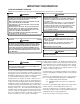
IMPORTANT INFORMATION SAFE REFRIGERANT HANDLING While these items will not cover every conceivable situation, they should serve as a useful guide. WARNING WARNING REFRIGERANTS ARE HEAVIER THAN AIR. THEY CAN "PUSH OUT" THE TO AVOID TO AVOID POSSIBLE EXPLOSION: • NEVER APPLY FLAME OR STEAM TO A REFRIGERANT CYLINDER. IF YOU OXYGEN IN YOUR LUNGS OR IN ANY ENCLOSED SPACE.
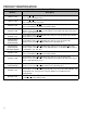
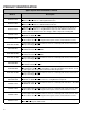
PRODUCT IDENTIFICATION Split System Heat Pumps R410A M odel # GSZ13**1AA Goodman Split Z R410A Heat Pum p 13 Seer R410A heat pump units. Initial release with Regal Beloit motor. GSZ13**1AB Goodman Split Z R410A Heat Pum p 13 Seer R410A heat pump units. Initial release with Broad Ocean m otor. SSZ140**1AA Special High Feature Split Z R410A heat pump 14 Seer heat pump units. Initial release of Goodman 14 SEER Heat Pum p R410A.
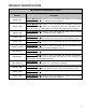
PRODUCT IDENTIFICATION Split System Heat Pumps R410A Model # Description ASZ130**1AA Amana® Brand Split Z R410A heat pump 13 Seer heat pump units. Initial release of Amana® Brand 13 SEER Heat Pump R410A. ASZ140**1AA Amana® Brand Split Z R410A heat pump 14 Seer heat pump units. Initial release of Amana® Brand 14 SEER Heat Pump R410A. ASZ140**1AB Amana® Brand Split Z R410A heat pump 14 Seer heat pump units.
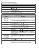
PRODUCT IDENTIFICATION Split System Air Conditioners R410A Model # GSX130**1AA G oodman Split X Condenser 13 Seer condensing units. Introduction of Goodman 13 SEER R-410A Condensers with Regal Beloit motors GSX130**1AB Goodman Split X Condenser 13 Seer condensing units. Introduction of Goodman 13 SEER R-410A Condensers with Broad Ocean motors. GSX130**1BA G oodman Split X Condenser 13 Seer condensing units. Introduction of Goodman 13 SEER R-410A Condensers, using Quantum Leap coils.
PRODUCT IDENTIFICATION Split System Air Conditioners R410A Model # Description ASX130**1AA Amana® Brand Split X Condenser 13 Seer condensing units. Initial release new models of Amana® Brand Deluxe 13 SEER AC R410A conditioners. ASX130**1BA Amana® Brand Split X Condenser 13 Seer condensing units. Introduction of Amana® Brand 13 SEER R-410A Condensers, using Quantum Leap Coils. Units will have new louvers since units are smaller. Piston size change; other components unchanged.
PRODUCT IDENTIFICATION Single Piece Air Handlers 8 Model # Description ARUF****16AA A Single Piece R Multi-Position PSC Motor Unpainted Flowrater Introducation of new 13 SEER Air Handler Models. All Models will be suitable for use with R22 and R-410A ARUF364216AB A Single Piece R Multi-Position PSC Motor Unpainted Flowrater.Revision replaces the current spot welded blower housing with the same cinched or crimped design used on the 80% furnace line.
PRODUCT IDENTIFICATION Single Piece Air Handlers Model # Description AEPF****16AA A Single Piece E Multi-Position Variable-Speed Painted Flowrator. Introducation of new 13 SEER Air Handler Models. All Models will be suitable for use with R-22 and R-410A AEPF****16BA A Single Piece E Multi-Position Variable-Speed Painted Flowrator. Revision introduces new models adding lower kw hit kits on the S&R plate AEPF****16BB A Single Piece E Multi-Position Variable-Speed Painted Flowrator.
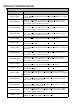
PRODUCT IDENTIFICATION MBR/MBE Air Handlers Model # Description MBR****AA-1AA Modular Blower R Multi-Position PSC Motor. Introduces module blower with PSC blower motor. MBE****AA-1AA M odular Blower E Multi-Position Variable-Speed. Introduces module blower with variable speed blower motor. MBE****AA-1BA Modular Blower E Multi-Position Variable-Speed.
PRODUCT IDENTIFICATION S S Z 14 36 1 A BRAND: ® G: Goodman (Standard Feature Set) MINOR REVISION: A: Initial Release SEER: SEER Rating S: Goodman® (High Feature Set) A: Amana® Brand Deluxe D: Deluxe Goodman® PRODUCT FAMILY: S: Split System PRODUCT TYPE: X: Condenser R-410A Z: Heat Pump R-410A A NOMINAL CAPACITY: 018: 1.5 Tons 024: 2 Tons 030: 2.5 Tons 036: 3 Tons 042: 3.
PRODUCT IDENTIFICATION C A P F 1824 A 6 A EXPANSION DEVICE: F: Flowrater PRODUCT TYPE: C: Indoor Coil REVISION A: Revision REFRIGERANT CHARGE: 6: R-410A or R-22 2: R-22 4: R-410a CABINET FINISH: U: Unpainted P: Painted N: Unpainted Case NOMINAL WIDTH FOR GAS FURNACE A: Fits 14" Furnace Cabinet B: Fits 17 1/2" Furnace Cabinet C: Fits 21" Furnace Cabinet D: Fits 24 1/2" Furnace Cabinet N: Does Not Apply (Horizontal Slab Coils) APPLICATION A: Upflow/Downflow Coil H: Horizontal A Coil S: Horizonta
PRODUCT IDENTIFICATION A W PRODUCT TYPE: A: Air Handler U F 3642 1 6 EXPANSION DEVICE: F: Flowrater T: TXV (Expansion Device) A MINOR REVISION* MAJOR REVISION* CABINET FINISH: U: Unpainted P: Paited N: Uncased APPLICATION C: Ceiling Mount PSC Motor D: Downflow PSC Motor E: Multi-Position Varible-Speed Motor S: Energy-Efficient Motor R: Multi-Position PSC Motor T: Coated Coils W: Wall Mount PSC Motor A REFRIGERANT CHARGE: No Digit: R-22 Only 6: R-410A or R-22 ELECTRICAL: 1: 208-230V/1ph/60Hz
ACCESSORIES ASX13 Model Description ASX13 018 ASX13 024 ASX13 030 ASX13 036 ASX13 042 ASX13 0418 ASX13 060 X X X X X X X X X X X X X X ASC01 Anti-Short Cycle Kit X X X X CSR-U-1 Hard-start Kit X X X X CSR-U-2 Hard-start Kit CSR-U-3 Hard-start Kit 1 X FSK01A Freeze Protection Kit X TX2N4³ TXV Kit X TX3N42 TXV Kit 2 TXV Kit TX5N4 X X X X X X GSX13 GSX13 018 GSX13 024 GSX13 030 GSX13 036 GSX13 042 GSX13 0418 GSX13 060 Anti-Short Cycle Kit X X
ACCESSORIES DSX/SSX16 D/SSX16 024 D/SSX16 030 D/SSX16 036 D/SSX16 042 D/SSX16 048 D/SSX16 060 Anti-Short Cycle Kit X X X X X X CSR-U-1 Hard-start Kit X X X CSR-U-2 Hard-start Kit X X X CSR-U-3 Hard-start Kit X X X X X X X X Model Description ASC01 1 X FSK01A Freeze Protection Kit X TX2N4³ TXV Kit X TX3N4³ TXV Kit TX5N4³ TXV Kit X X X X 1 Installed on indoor coil Required for heat pump applications where ambient temperatures fall below 0°F with 50% or high
ACCESSORIES ASX18 ASX18 036 ASX18 048 ASX18 060 Anti-Short Cycle Kit X X X CSR-U-1 Hard-start Kit X CSR-U-2 Hard-start Kit X X X CSR-U-3 Hard-start Kit X X X X X X Model Description ASC01 1 FSK01A Freeze Protection Kit TX2N4³ TXV Kit TX3N4³ TXV Kit TX5N4³ TXV Kit 1 2 X X Installed on indoor coil Required for heat pump applications where ambient temperatures fall below 0°F with 50% or higher relative humidy.
ACCESSORIES ASZ13 ASZ13 018 ASZ13 024 ASZ13 030 ASZ13 036 ASZ13 042 ASZ13 048 ASZ13 060 Model Description AFE18-60A All-Fuel Kit X X X X X X X ASC01 Anti-Short Cycle Kit X X X X X X X CSR-U-1 Hard-start Kit X X X X CSR-U-2 Hard-start Kit CSR-U-3 Hard-start Kit X X X X X X FSK01A1 Freeze Protection Kit X X X X X X X OT/EHR18-60 Emergency Heat Relay kit X X X X X X X OT18-60A² Outdoor Thermostat w/ Lockout Stat X X X X X X X TX2N4³ TXV Kit
ACCESSORIES DSZ/SSZ16 Model Description D/SSZ16 024 D/SSZ16 030 D/SSZ16 036 D/SSZ16 042 D/SSZ16 048 D/SSZ16 060 AFE18-60A All-Fuel Kit X X X X X X ASC01 Anti-Short Cycle Kit X X X X X X CSR-U-1 Hard-start Kit X X X CSR-U-2 Hard-start Kit X X X X CSR-U-3 Hard-start Kit X X X X X X 1 FSK01A Freeze Protection Kit X X OT/EHR18-60 Emergency Heat Relay Kit X X X X X X OY/EH R18-60 Emergency Heat Relay Kit X X X X X X OT18-60A² Outdoor Thermostat w/
ACCESSORIES ASZ18 Model Description ASZ18 036 ASZ18 048 ASZ18 060 AFE18-60A All-Fuel Kit X X X ASC01 Anti-Short Cycle Kit X X X CSR-U-1 Hard-start Kit X CSR-U-2 Hard-start Kit X X X CSR-U-3 Hard-start Kit X X 1 FSK01A Freeze Protection Kit X X X OT/EHR18-60 Emergency Heat Relay Kit X X X OY/EH R18-60 Emergency Heat Relay Kit X X X OT18-60A² Outdoor Thermostat w/ Lockout Stat X X X TX2N4³ TXV Kit TX3N4³ TXV Kit TX5N4³ TXV Kit X X X 1 Installed on indo
ACCESSORIES EXPANSION VALVE KITS For Applications requiring 1/4 FLARE CONNECTION BULB TO BE LOCATED AT 10 OR 2 O'CLOCK a field installed access fitting BULB SUCTION LINE EVAPORATOR COIL PISTON SEAL SUPPLIED W/ KIT SEAL SUPPLIED W/ KIT SEAL DISTRIBUTOR BODY EXPANSION VALVE TAILPIECE REMOVE BEFORE INSTALLING EXPANSION VALVE 3/8"SWEAT 7/8" NUT For Applications not requiring 1/4' FLARE CONNECTION a field installed access fitting BULB TO BE LOCATED AT 10 OR 2 O'CLOCK BULB SUCTION LINE PISTON EX
ACCESSORIES FSK01A FREEZE THERMOSTAT KIT Wire Nut Y Bl ac k Y k ac Bl Wire Nut Install Line Thermostat Here Install Line Thermostat Here Wire Nut Bla ck Y Bla ck Wire Nut Y ASC01A ANTI-SHORT -CYCLE CONTROL KIT SHORT CYCLE PROTECTOR Y1 R1 Y2 R2 YELLOW 1 CONTACTOR T2 T1 Y BLACK 1 THERMOSTAT WIRE L2 L1 C BLACK 1 UNIT TERMINAL BOARD 21
ACCESSORIES COIL ACCESSORIES COIL MODEL TX2N4 TXV KIT TX3N4 TXV KIT CA*F18246* X X CA*F30306* X CA*F36426* X TX5N4 TXV KIT FSK01A FREEZE PROTECTION KIT X X X X CHPF18246* X X CHPF30306* X X CHPF36426* X CSCF1824N6* X X X CSCF303N6* X CSCF3642N6* X X X X HKR SERIES ELECTRIC HEAT KITS ELECTRIC HEAT KIT APPLICATIONS - MBR & MBE ELECTRIC HEAT KIT BLOWER NO HEAT HKR-03* HKR05-(C)' HKR-06* MBR0800AA-1AA - X X X HKR-08(C)* HKR-10(C)* HKR-15(C)* HKR-20(C)* HKR-21(C)* ^HKR3-1
ACCESSORIES ELECTRIC HEAT KIT APPLICATIONS - ARUF ARUF1729 1/16 ARUF1824 1/16 ARUF1931 1/16 ARUF3030 1/16 ARUF3642 1/16 ARUF3743 1/16 ARUF4860 1/16 HKR-03* X X X X X X X HKR-05*, HKR-05C* X X X X X X X HKR-06* X X X X X X X HKR-08*, HKR-08C* X1 X1 X1 X X X X HKR-10*, HKR-10C* X1 X1 X1 X1 X X X 2 2 2 2 3 3 X 3 X X 3 X X HKR-15C* X X X X X X X 2 HKR-21C* X 2 ^ HKR3-15* X2 X3 X3 X ^ HKR3-20* X2 X3 X3 X HKR-20C* 3 X X 3 * Rev
ACCESSORIES ELECTRIC HEAT KIT APPLICATIONS - AEPF AEPF183016 HKR-05*, HKR-05C* X HRK-08*, HKR-08C X HKR-10*, HKR-10C X 1 HKR-15C* AEPF303616 AEPF313716 AEPF426016 X X X X X 1 X X 1 X X 2 HKR-20C* X HKR-21C X 2 * Revision level that may or may not be designated C Circuit Breaker option 1 This heater kit can be used ONLY for 1000 CFM or higher applications 2 This heater kit can be used ONLY for 1200 CFM or higher applications ELECTRIC HEAT KIT APPLICATIONS - ASPF ASPF183016 ASPF303
PRODUCT DESIGN This section gives a basic description of cooling unit operation, its various components and their basic operation. Ensure your system is properly sized for heat gain and loss according to methods of the Air Conditioning Contractors Association (ACCA) or equivalent. CONDENSING UNIT The condenser air is pulled through the condenser coil by a direct drive propeller fan. This condenser air is then discharged out of the top of the cabinet.
PRODUCT DESIGN The ASX [16 & 18], ASZ [16 & 18], DSX16 and DSZ16 series split system units use a two-stage scroll compressor. The two-step modulator has an internal unloading mechanism that opens a bypass port in the first compression pocket, effectively reducing the displacement of the scroll. The opening and closing of the bypass port is controlled by an internal electrically operated solenoid.
PRODUCT DESIGN CAPACITY CONTROL During the compression process, there are several pockets within the scroll that are compressing gas. Modulation is achieved by venting a portion of the gas in the first suction pocket back to the low side of the compressor thereby reducing the effective displacement of the compressor. See Figure A. Full capacity is achieved by blocking these vents, increasing the displacement to 100%.
SYSTEM OPERATION COOLING HEATING The refrigerant used in the system is R-410A. It is a clear, colorless, non-toxic and non-irritating liquid. R-410A is a 50:50 blend of R-32 and R-125. The boiling point at atmospheric pressure is -62.9°F. The heating portion of the refrigeration cycle is similar to the cooling cycle. By energizing the reversing valve solenoid coil, the flow of the refrigerant is reversed. The indoor coil now becomes the condenser coil, and the outdoor coil becomes the evaporator coil.
SYSTEM OPERATION DEFROST CYCLE HEATING CYCLE The defrosting of the outdoor coil is jointly controlled by the defrost control board and the defrost thermostat. The reversing valve on the GSZ, SSZ, ASZ and DSZ models is energized in the cooling cycle through the "O" terminal on the room thermostat. Solid State Defrost Control During operation the power to the circuit board is controlled by a temperature sensor, which is clamped to a feeder tube entering the outdoor coil.
SYSTEM OPERATION COOLING CYCLE Reversing Valve (Energized) Indoor Coil Outdoor Coil Accumulator Thermostatic Expansion Valve Bi-Flow Filter Dryer Check Valve HEATING CYCLE Reversing Valve (De-Energized) Indoor Coil Outdoor Coil Accumulator Thermostatic Expansion Valve Bi-Flow Filter Dryer Check Valve 30
SYSTEM OPERATION EXPANSION VALVE/CHECK VALVE ASSEMBLY IN COOLING OPERATION EXPANSION VALVE/CHECK VALVE ASSEMBLY IN HEATING OPERATION Most expansion valves used in current Amana® Brand Heat Pump products use an internally checked expansion valve. This type of expansion valve does not require an external check valve as shown above. However, the principle of operation is the same.
SYSTEM OPERATION AFE18-60A CONTROL BOARD DESCRIPTION The AFE18 control is designed for use in heat pump applications where the indoor coil is located above/downstream of a gas or fossil fuel furnace. It will operate with single and two stage heat pumps and single and two stage furnaces. The AFE18 control will turn the heat pump unit off when the furnace is turned on. An anti-short cycle feature is also incorporated which initiates a 3 minute timed off delay when the compressor goes off.
TROUBLESHOOTING CHART COOLING/H P ANALYSIS CHART Pow er Failure Blow n Fus e Unbalanced Pow er, 3PH Loose Connec tion Shorted or Broken Wires Open Fan Ov erload Faulty Thermos tat Faulty Transf ormer Shorted or Open Capacitor Internal Compres s or Overload Open Shorted or Grounded Compress or Compress or Stuc k Faulty Compress or Contactor Faulty Fan Relay Open Control Circ uit Low V oltage Faulty Evap.
SERVICING S-1 S-2 S-3 S-3A S-3B S-3C S-3D S-4 S-5 S-6 S-7 S-8 S-9 S-10 S-11 S-12 S-13 S-15 S-15A S-15B S-16A S-16B S-16C S-16D S-16E S-16F S-17 S-17A S-17B S-17C S-17D S-18 S-21 S-24 S-25 S-26 Checking Voltage .......................................... 35 Checking Wiring ............................................ 35 Checking Thermostat, Wiring & Anticipator .. 35 Thermostat & Wiring ..................................... 35 Cooling Anticipator ........................................
SERVICING S-2 CHECKING WIRING S-1 CHECKING VOLTAGE 1. Remove outer case, control panel cover, etc., from unit being tested. With power ON: HIGH VOLTAGE! Disconnect ALL power before servicing or installing. Multiple power sources may be present. Failure to do so may cause property damage, personal injury or death. WARNING Line Voltage now present. 2.
SERVICING 4. Check the continuity of the thermostat and wiring. Repair or replace as necessary. Resistance Heaters 1. Set room thermostat to a higher setting than room temperature so both stages call for heat. element helping the thermostat call for the next cooling cycle. This prevents the room temperature from rising too high before the system is restarted. A properly sized anticipator should maintain room temperature within 1 1/2 to 2 degree range. 2.
SERVICING S-4 CHECKING TRANSFORMER AND CONTROL CIRCUIT With power ON: WARNING Line Voltage now present. HIGH VOLTAGE! Disconnect ALL power before servicing or installing. Multiple power sources may be present. Failure to do so may cause property damage, personal injury or death. A step-down transformer (208/240 volt primary to 24 volt secondary) is provided with each indoor unit. This allows ample capacity for use with resistance heaters. The outdoor sections do not contain a transformer.
SERVICING S-7 CHECKING CONTACTOR AND/OR RELAYS T2 HIGH VOLTAGE! Disconnect ALL power before servicing or installing. Multiple power sources may be present. Failure to do so may cause property damage, personal injury or death. The compressor contactor and other relay holding coils are wired into the low or line voltage circuits. When the control circuit is energized, the coil pulls in the normally open contacts or opens the normally closed contacts.
SERVICING WARNING Line Voltage now present. 4 3 OHMMETER 2 5 1 TESTING FAN RELAY 4. Using an ohmmeter, test between 2 and 4 - should read continuous . Test between 5 and 6 - should read open. 5. If not as above, replace the relay.
SERVICING DIAGNOSTICS TABLE Status LED Green “POWER” Red “TRIP” Status LED Description Module has power Thermostat demand signal Status LED Troubleshooting Information Supply voltage is present at module terminals 1. Compressor protector is open Y1 is present, but the 2. Outdoor unit power disconnect is open compressor is not 3. Compressor circuit breaker or fuse(s) is open running 4. Broken wire or connector is not making contact 5. Low pressure switch open if present in system 6.
SERVICING S-11 CHECKING LOSS OF CHARGE PROTECTOR (Heat Pump Models) The loss of charge protector senses the pressure in the liquid line and will open its contacts on a drop in pressure. The low pressure control will automatically reset itself with a rise in pressure. The low pressure control is designed to cut-out (open) at approximately 21 PSIG. It will automatically cut-in (close) at approximately 50 PSIG. Test for continuity using a VOM and if not as above, replace the control.
SERVICING The discharge check valve closes off high side pressure to the compressor after shut down allowing equalization through the scroll flanks. Equalization requires only about ½ second. To prevent the compressor from short cycling, a Time Delay Relay (Cycle Protector) has been added to the low voltage circuit. OHMMETER RELAY, START A potential or voltage type relay is used to take the start capacitor out of the circuit once the motor comes up to speed. This type of relay is position sensitive.
SERVICING S-16A CHECKING FAN AND BLOWER MOTOR WINDINGS (PSC MOTORS) The auto reset fan motor overload is designed to protect the motor against high temperature and high amperage conditions by breaking the common circuit within the motor, similar to the compressor internal overload. However, heat generated within the motor is faster to dissipate than the compressor, allow at least 45 minutes for the overload to reset, then retest. HIGH VOLTAGE! Disconnect ALL power before servicing or installing.
- Does removing panel or filter reduce "puffing"? - Check/replace filter. - Check/correct duct restrictions. - Adjust to correct blower speed setting. - Incorrect or dirty filter(s). - Incorrect supply or return ductwork. - Incorrect blower speed setting. - Varies up and down or intermittent. - "Hunts" or "puffs" at high CFM (speed). ---- - Check line voltage for variation or "sag". - Check low voltage connections (G, Y, W, R, C) at motor, unseated pins in motor harness connectors.
- Turn power OFF prior to repair. - Turn power OFF prior to repair. - Check for loose blower housing, panels, etc. - Check for air whistling thru seams in ducts, cabinets or panels. - Check for cabinet/duct deformation. - Does removing panel or filter reduce "puffing"? - Check/replace filter. - Check/correct duct restrictions. - Adjust to correct blower speed setting. - Loose blower housing, panels, etc. - High static creating high blower speed. - Air leaks in ductwork, cabinets, or panels.
SERVICING S-16C CHECKING ECM MOTOR WINDINGS HIGH VOLTAGE! Disconnect ALL power before servicing or installing. Multiple power sources may be present. Failure to do so may cause property damage, personal injury or death. The MBE/AEPF products use a General Electric ECMTM motor. This motor provides many features not available on the traditional PSC motor. These features include: • • • • Improved Efficiency Constant CFM Soft Start and Stop Improved Humidity Control MOTOR SPEED ADJUSTMENT 2.
SERVICING AEPF DIPSWITCH FUNCTIONS Cooling/Heat Pump Operation Model Switch 5 Switch 6 CFM OFF OFF ON OFF OFF ON ON ON OFF OFF 1,200 1,000 800 600 1,600 1,400 1,200 1,000 2,000 1,800 1,600 1,200 MBE1200 MBE1600 ON OFF OFF ON ON ON OFF ON OFF ON OFF OFF ON ON Dipswitch 1/2 & 7/8 AEPF 1830 Heating Element Switch Position Switch Position Emergency Heat Pump Backup With Backup (kw) 1 2 7 8 UP TO 10 OFF OFF OFF OFF 1100 1210 UP TO 10 ON OFF OFF OFF 890 935 5 OFF ON
SERVICING S-16E BLOWER PERFORMANCE DATA SPEED HIGH MEDIUM LOW STATIC MBR800**-* SCFM MBR1200**-* SCFM MBR1600**-* SCFM MBR2000**-* SCFM 0.1 1,240 1,500 1,800 2,160 0.2 1,170 1,460 1,740 2,080 0.3 1,120 1,360 1,680 1,990 0.4 1,060 1,280 1,610 1,890 0.5 980 1,200 1,520 1,790 0.6 900 1,110 1,430 1,690 0.1 900 1,380 1,540 1,730 0.2 850 1,320 1,490 1,670 0.3 790 1,270 1,450 1,590 0.4 740 1,200 1,400 1,520 0.5 680 1,140 13,560 1,420 0.
SERVICING S-17 CHECKING COMPRESSOR WARNING Hermetic compressor electrical terminal venting can be dangerous. When insulating material which supports a hermetic compressor or electrical terminal suddenly disintegrates due to physical abuse or as a result of an electrical short between the terminal and the compressor housing, the terminal may be expelled, venting the vapor and liquid contents of the compressor housing and system.
SERVICING Do not use a low voltage output instrument such as a voltohmmeter. 1. Operate the system and measure compressor current. Cycle the unloader ON and OFF at 10 second intervals. The compressor amperage should go up or down at least 25 percent. 2. If step one does not give the expected results, shut unit off. Apply 18 to 28 volt ac to the unloader molded plug leads and listen for a click as the solenoid pulls in.
SERVICING 3. Connect good capacitors of the right MFD and voltage rating into the circuit as shown. 4. With power ON, close the switch. If no voltage is registered at the coil terminals, check the operation of the thermostat and the continuity of the connecting wiring from the "O" terminal of the thermostat to the unit. WARNING Line Voltage now present. A. If the compressor starts and continues to run, the cause for failure is somewhere else in the system. B. If the compressor fails to start - replace.
SERVICING 3. Check the temperature at which the control opens its contacts by raising the temperature of the control. Part # 0130M00009P which is used on 2 and 2.5 ton units should open at 60°F ± 5°F. Part # 0130M00001P which is used on 3 thru 5 ton units should open at 75°F ± 6°F. 4. If not as above, replace control.
SERVICING 1.4 The compressor and condenser fan are turned off and after a 65 second delay off, the relay on the EBTDR board is de-energized and the blower is turned off. 3.4 The heat pump is turned off and after a 65 second delay off, the relay on the EBTDR board is de-energized and the blower motor is turned off. 2.0 Heating Operation 4.0 Heating Operation 2.1 On a demand for heat, the room thermostat energizes “W1” and 24Vac is supplied to heat sequencer, HR1, on the heater assembly.
SERVICING 4.5 When the first stage heat demand “Y” is satisfied, the room thermostat will remove the 24Vac from “G” and “Y”. The heat pump is turned off and the blower motor turns off after a 65 second off delay. 5.0 Defrost Operation On heat pump units, when the room thermostat is set to the heating mode, the reversing valve is not energized. As long as the thermostat is set for heating, the reversing valve will be in the de-energized position for heating except during a defrost cycle. 5.
SERVICING remove the 24Vac from HR2. The contacts on HR2 will open between 30 to 70 seconds and heater elements #3 and #4 will be turned off and the blower motor will change to low speed. On most digital/electronic thermostats, “W2” will remain energized until the first stage demand “W1” is satisfied and then the “W1” and “W2” demands will be removed. 2.3 When the “W1” heat demand is satisfied, the room thermostat will remove the 24Vac from “E/W1” and the VSTB removes the 24Vac from HR1.
SERVICING 5.0 DEFROST OPERATION On heat pump units, when the room thermostat is set to the heating mode, the reversing valve is not energized. As long as the thermostat is set for heating, the reversing valve will be in the de-energized position for heating except during a defrost cycle. 5.1 The heat pump will be on and operating in the heating mode as described the Heating Operation in section 4. 5.
SERVICING For the 3rd and 4th heater elements to operate on a second stage heat demand, the PJ4 jumper on the VSTB inside the MBE/AEPF must be cut. With the PJ4 jumper cut, the VSTB will run the blower motor on low speed on a “W1” only demand. If the first stage heat demand, “W1” cannot be satisfied by the heat pump, the temperature indoors will continue to drop.
SERVICING The outdoor fan will change to high speed operation. If the “Y2” demand is present and becomes satisfied, the thermostat will remove the “Y2” demand and the VSTB will remove the 24Vac from “Y/Y2” at the heat pump. The blower will drop to 60% of the programmed cfm and the outdoor fan will change to low speed. On most digital/ electronic thermostats, “Y2” will remain energized until the first stage heating demand “Y1” is satisfied and then the “G”, “Y1” and “Y2” demands will be removed. 5.
SERVICING Alternately, the system CFM can be determined by operating the electric heaters and indoor blower WITHOUT having the compressor in operation. Measure the temperature rise as close to the blower inlet and outlet as possible. If other than a 240V power supply is used, refer to the BTUH CAPACITY CORRECTION FACTOR chart below. BTUH CAPACITY CORRECTION FACTOR SUPPLY VOLTAGE 250 230 220 208 MULTIPLICATION FACTOR 1.08 .92 .84 .75 ELECTRIC HEATER CAPACITY BTUH HTR KW 3.0 KW 4.7 KW 6.0 KW 7.
SERVICING 2. Using an ohmmeter, test across the fuse link for continuity - no reading indicates the link is open. Replace as necessary. NOTE: The link is designed to open at approximately 333°F. DO NOT WIRE AROUND - determine reason for failure. S-62 CHECKING HEATER ELEMENTS WARNING Disconnect ALL power before servicing. 1. Disassemble and remove the heating element. BRAZING MATERIALS IMPORTANT NOTE: Torch heat required to braze tubes of various sizes is proportional to the size of the tube.
SERVICING IMPORTANT NOTE: Because of the potential damage to compressors, do not allow suction pressure at service valve to drop below 20 PSIG when pumping unit system down for repair. Outdoor section, depending on line set length and amount of charge in system, may not be able to hold the entire system charge. This is the most important part of the entire service procedure.
SERVICING CAUTION Use refrigerant certified to AHRI standards. Used refrigerant may cause compressor damage and will void the warranty. Most portable machines cannot clean used refrigerant to meet AHRI standards. CAUTION Operating the compressor with the suction valve closed will void the warranty and cause serious compressor damage. Charge the system with the exact amount of refrigerant. Refer to the specification section or check the unit nameplates for the correct refrigerant charge.
SERVICING S-105A PISTON CHART FOR ASX13, GSX13, SSX14, ASX14, ASZ13, GSZ13 units Remote Condenser A/GSX130181A Orifice Size 0.049 Remote Heat Pump A/GSZ130181 Orifice Size 0.049 A/GSX130181B 0.051 A/GSZ130241 0.057 A/GSX130241A 0.053 A/GSZ130301 0.063 A/GSX130241B 0.057 A/GSZ130361 0.068 A/GSX130301 0.059 A/GSZ130421 0.074 A/GSX130301B 0.061 A/GSZ130481 0.078 A/GSX130361A 0.068 A/GSZ130601 0.088 A/GSX130361B 0.070 SSZ140361A* 0.071 A/GSX130421A 0.074 SSZ140421A* 0.
SERVICING Pressure vs. Temperature Chart R-410A PSIG 12 14 16 18 20 22 24 26 28 30 32 34 36 38 40 42 44 46 48 50 52 54 56 58 60 62 64 66 68 70 72 74 76 78 80 82 84 86 88 90 92 94 96 98 100 102 104 106 108 110 112 °F -37.7 -34.7 -32.0 -29.4 -36.9 -24.5 -22.2 -20.0 -17.9 -15.8 -13.8 -11.9 -10.1 -8.3 -6.5 -4.5 -3.2 -1.6 0.0 1.5 3.0 4.5 5.9 7.3 8.6 10.0 11.3 12.6 13.8 15.1 16.3 17.5 18.7 19.8 21.0 22.1 23.2 24.3 25.4 26.4 27.4 28.5 29.5 30.5 31.2 32.2 33.2 34.1 35.1 35.5 36.9 PSIG 114.0 116.0 118.0 120.0 122.
SERVICING REQUIRED LIQUID LINE TEMPERATURE LIQUID PRESSURE AT SERVICE VALVE (PSIG) 189 195 202 208 215 222 229 236 243 251 259 266 274 283 291 299 308 317 326 335 345 354 364 374 384 395 406 416 427 439 450 462 474 486 499 511 8 58 60 62 64 66 68 70 72 74 76 78 80 82 84 86 88 90 92 94 96 98 100 102 104 106 108 110 112 114 116 118 120 122 124 126 128 REQUIRED SUBCOOLING TEMPERATURE (°F) 10 12 14 16 56 54 52 50 58 56 54 52 60 58 56 54 62 60 58 56 64 62 60 58 66 64 62 60 68 66 64 62 70 68 66 64 72 70 68 66
SERVICING S-106 OVERFEEDING Superheat Formula = Suct. Line Temp. - Sat. Suct. Temp. Overfeeding by the expansion valve results in high suction pressure, cold suction line, and possible liquid slugging of the compressor. EXAMPLE: 1. Check for an overcharged unit by referring to the cooling performance charts in the servicing section. a. Suction Pressure = 143 b. Corresponding Temp. °F. = 50 c. Thermometer on Suction Line = 61°F. To obtain the degrees temperature of superheat, subtract 50.0 from 61.0°F.
SERVICING 4. Review the technical information manual or specification sheet for the model being serviced to obtain the design subcooling. 5. Compare the hi-pressure reading to the "Required Liquid Line Temperature" chart (page 43). Find the hi-pressure value on the left column. Follow that line right to the column under the design subcooling value. Where the two intersect is the required liquid line temperature.
SERVICING 2. Remove the orifice or tube strainer assembly and replace. 3. Replace liquid line drier, evacuate and recharge. CHECKING EQUALIZATION TIME During the "OFF" cycle, the high side pressure bleeds to the low side through the fixed orifice restriction device. Check equalization time as follows: 1. Attach a gauge manifold to the suction and liquid line dill valves. S-114 NON-CONDENSABLES If non-condensables are suspected, shut down the system and allow the pressures to equalize.
SERVICING NOTE: At least twelve (12) inches of the suction line immediately out of the compressor stub must be discarded due to burned residue and contaminates. 1. Remove compressor discharge line strainer. 2. Remove the liquid line drier and expansion valve. 3 Purge all remaining components with dry nitrogen or carbon dioxide until clean. 4. Install new components including liquid line drier. 5. Braze all joints, leak test, evacuate, and recharge system. 6.
SERVICING 4. Two-Stage Condensing Unit: The maximum length of tubing must not exceed 80 feet where indoor coil is located above the outdoor unit. NOTE: When the outdoor unit is located above the indoor coil, the maximum vertical rise must not exceed 25 feet. If the maximum vertical rise exceeds 25 feet, premature compressor failure will occur due to inadequate oil return. 5. Most refrigerant tubing kits are supplied with 3/8"thick insulation on the vapor line.
SERVICING Remember, 3/8" liquid tubing is required for all long line set applications. Mounting the condensing unit above the evaporator coil will require oil traps at equal intervals along the suction line. Install 1 oil trap for a height difference of 15-25 feet between indoor and outdoor units. Install 2 oil traps for a difference of 26-50 feet, 3 for 51-100 feet, and 4 for 101-150 feet. Fig 7.
SERVICING 3. Add the two readings together. TOTAL EXTERNAL STATIC NOTE: Both readings may be taken simultaneously and read directly on the manometer if so desired. 4. Consult proper table for quantity of air. If external static pressure is being measured on a furnace to determine airflow, supply static must be taken between the "A" coil and the furnace.
ACCESSORIES WIRING DIAGRAMS HIGH VOLTAGE! DISCONNECT ALL POWER BEFORE SERVICING OR INSTALLING THIS UNIT. MULTIPLE POWER SOURCES MAY BE PRESENT. FAILURE TO DO SO MAY CAUSE PROPERTY DAMAGE, PERSONAL INJURY OR DEATH.
ACCESSORIES WIRING DIAGRAMS HIGH VOLTAGE! DISCONNECT ALL POWER BEFORE SERVICING OR INSTALLING THIS UNIT. MULTIPLE POWER SOURCES MAY BE PRESENT. FAILURE TO DO SO MAY CAUSE PROPERTY DAMAGE, PERSONAL INJURY OR DEATH.
ACCESSORIES WIRING DIAGRAMS HIGH VOLTAGE! DISCONNECT ALL POWER BEFORE SERVICING OR INSTALLING THIS UNIT. MULTIPLE POWER SOURCES MAY BE PRESENT. FAILURE TO DO SO MAY CAUSE PROPERTY DAMAGE, PERSONAL INJURY OR DEATH.
ACCESSORIES WIRING DIAGRAMS HIGH VOLTAGE! DISCONNECT ALL POWER BEFORE SERVICING OR INSTALLING THIS UNIT. MULTIPLE POWER SOURCES MAY BE PRESENT. FAILURE TO DO SO MAY CAUSE PROPERTY DAMAGE, PERSONAL INJURY OR DEATH.
ACCESSORIES WIRING DIAGRAMS HIGH VOLTAGE! DISCONNECT ALL POWER BEFORE SERVICING OR INSTALLING THIS UNIT. MULTIPLE POWER SOURCES MAY BE PRESENT. FAILURE TO DO SO MAY CAUSE PROPERTY DAMAGE, PERSONAL INJURY OR DEATH.
ACCESSORIES WIRING DIAGRAMS HIGH VOLTAGE! DISCONNECT ALL POWER BEFORE SERVICING OR INSTALLING THIS UNIT. MULTIPLE POWER SOURCES MAY BE PRESENT. FAILURE TO DO SO MAY CAUSE PROPERTY DAMAGE, PERSONAL INJURY OR DEATH.
ACCESSORIES WIRING DIAGRAMS BL 5 208 2 3 COM TR 8 240 1 9 9 8 R G 24V BL L2 4 L1 R HIGH VOLTAGE! DISCONNECT ALL POWER BEFORE SERVICING OR INSTALLING THIS UNIT. MULTIPLE POWER SOURCES MAY BE PRESENT. FAILURE TO DO SO MAY CAUSE PROPERTY DAMAGE, PERSONAL INJURY OR DEATH.
ACCESSORIES WIRING DIAGRAMS HIGH VOLTAGE! DISCONNECT ALL POWER BEFORE SERVICING OR INSTALLING THIS UNIT. MULTIPLE POWER SOURCES MAY BE PRESENT. FAILURE TO DO SO MAY CAUSE PROPERTY DAMAGE, PERSONAL INJURY OR DEATH.