
Datasheet


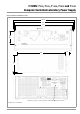


SYSKONP500, P800, P1500, P3000 and P4500
Computer Controlled Laboratory Power Supply
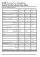
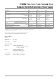
10 GMC-I Messtechnik GmbH
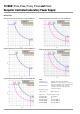
Electrical Data SYSKON P3000 / P4500
Article Number K363A K364A
Type SYSKON P3000-060-120 SYSKON P4500-060-180
Nominal Output Data Voltage setting range
Current setting range
Power
0 ... 60 V
0 ... 120 A
max. 3000 W
0 ... 60 V
0 ... 180 A
max. 4500 W
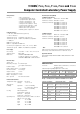
Output Characteristics (ppm and percentage values make reference to the respective setting or measured value)
Setting resolution Voltage
Current
1 mV
2 mA
1 mV
3.125 mA
Setting accuracy (at 23 5 °C) Auto-sensing mode
Without auto-sensing
Voltage
Current
0.07 % + 48 mV
0.07 % + 60 mV
0.1 % + 135 mA
0.1 % + 48 mV
0.1 % + 60 mV
0.15 % + 180 mA
Temperature coefficient
for / K setting
Voltage
Current
100 ppm
100 ppm
100 ppm
100 ppm
Setting accuracy via analog interface (at 23 5°C)
U
setnom
/U
setanalog
= 12; I
setnom
/I
setanalog
= 12/24/36
Voltage
Current
0.6 % + 150 mV
1.2 % + 180 mA
0.6 % + 150 mV
1.2 % + 240 mA
Static system deviation Auto-sensing mode
at 100% load fluctuation
Without auto-sensing
Voltage
Current
60 mV (< 500 μV/A)
96 mV (< 800 μV/A)
60 mA (< 1000 μA/V)
90 mV (< 500 μV/A)
144 mV (< 800 μV/A)
90 mA (< 1500 μA/V)
Static system deviation
with 10% line voltage fluctuation
Voltage
Current
7 mV
30 mA
10 mV
60 mA
Residual ripple Voltage
Current
Ripple: 10 Hz to 20 kHz
Ripple: 10 Hz to 1 MHz
Ripple + noise: 10 Hz to 10 MHz
Ripple + noise: 10 Hz to 10 MHz
60 mV
ss
75 mV
ss
90 mV
ss
/ 10 mV
eff
70 mA
eff
80 mV
ss
100 mV
ss
120 mV
ss
/ 15 mV
eff
100 mA
eff
Output voltage transient recovery time with sudden
load variation within range of 20 to 100% I
nom
and 20 to 100% U
nom
Tolerance
I = 10%
I = + 80% + approx. 800 A/ms
I = – 80 % + approx. 1200 A/ms
120 mV
400 μs
1200 μs
1900 μs
120 mV
500 μs
1600 μs
2500 μs
Output voltage over and undershooting with sudden
load variation within a range of 20 to 100% I
nom
and 20 to 100% U
nom
I = 10%
I = 80%
200 mV
1200 mV
250 mV
1300 mV
Setting time for output voltage
1)
where Uset step = 0 V 60 V
where Uset step = 60 V 1 V
where Uset step = 0 V 25 V
where Uset step = 25 V 1 V
Tolerance
No-load; nominal load
2)
No-load; nominal load
2)
No-load; nominal load
2)
No-load; nominal load
2)
120 mV
4 ms / 15 ms
70 ms / 11 ms
1.2 ms / 6 ms
16 ms / 6 ms
120 mV
7 ms / 19 ms
70 ms / 11 ms
2.4 ms / 11 ms
16 ms / 6 ms
Output capacitor
Sink (continuous power)
Nominal value
Power
4040 μF
80 W – 130 W
6060 μF
120 W – 195 W
Measuring Function
Measuring Range Voltage
Current
Power
– 16.384 … + 98.300 V
– 65.532 … + 196.600 A
U x I
– 16.384 … + 98.300 V
– 98.298 … + 294.900 A
U x I
Measuring resolution Voltage
Current
Power
2 mV
4 mA
100 mW
2 mV
6 mA
100 mW
Measuring accuracy (at 23 5°C) Voltage
Current
Power
0.07 % + 48 mV
0.6 % + 120 mA
0.7 % + 2 W
0.1 % + 48 mV
0.8 % + 180 mA
1 % + 3 W
Measured value temperature coefficient / K Voltage
Current
50 ppm + 0.6 mV
100 ppm + 2 mA
50 ppm + 0.8 mV
100 ppm + 3 mA
Measuring accuracy (at 23 ± 5 °C) at analog interface
U
actualnom
/ U
actualanalog
= 6; I
actualnom
/ I
actualanalog
= 6/12/18
Voltage
Current
0.6 % + 180 mV
1.2 % + 240 mA
0.8 % + 180 mV
1.2 % + 300 mA
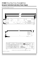
Protection and Additional Functions
Output overvoltage protection Trigger value
Response time
Setting Range
Setting resolution
Setting accuracy
3 … 80 V
20 mV
150 mV –20 m x I
a
200 μs
3 … 80 V
20 mV
150 mV –20 m x I
a
200 μs
Output overcurrent protection Trigger value
Response time
Setting Range
Setting resolution
Setting accuracy
6 … 160 A
50 mA
–
(1% + 500 mA)
–
40 mA/V x U
a
200 μs
9 … 240 A
100 mA
–
(1% + 700 mA)
–
60 mA/V x U
a
200 μs
Reverse polarity protection load capacity Continuous 120 A 180 A
Reverse voltage withstand capacity Continuous 70 V – 70 V –
Auto-sensing mode Compensatable voltage drop Per output lead 1 V 1 V